background image

23

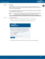
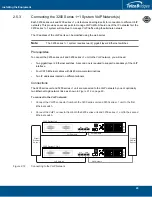
Installing the Equipment

2.4.5

Powering Up

The 3200 series gateway is furnished with two AC or DC power connections. Only once all other 
equipment installation work has been completed should the 3200 series gateway be powered up. 

2.4.5.1

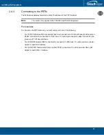
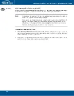
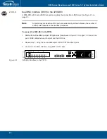
Connecting to AC Power

Prerequisites

To power the 3200 series gateway, you will need:

One to two power sources (138W).

Two power cables for the 3200 series gateway.

The 3200 series gateway AC model is furnished with two AC power connectors.

To connect to AC Power:

1.

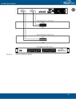
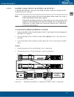
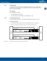
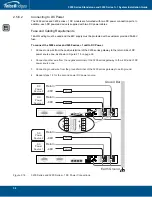
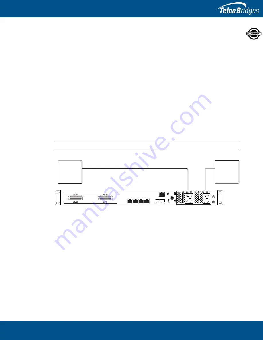
Connect an AC power cable between the AC connector of the 3200 series gateway and an AC 
supply. See 

Figure


2.8 on page

 23. 

Note

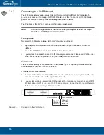
It is important to connect both power supplies in order to avoid setting off the audible alarm.

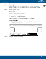
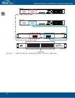
Figure


2.8

3200 Series Gateway AC Power Connection

MGMT0

ETH

VOIP

0

1

0

1

TMS

0

1

A

C

Power

So

u

rce 1

A

C

Power

So

u

rce 2

Содержание 3200 Series Gateway 1+1

Страница 1: ...Installation Guide 3200 Series Gateway Standalone 3200 Series Gateway 1 1 June 1 2016...

Страница 2: ...ridges is committed to continually improving product designs as a result product specifications may be subject to change without notification 2003 2016 TelcoBridges All rights reserved TelcoBridges Tm...

Страница 3: ...unit This term is used when a description applies to all variations of the 3200 series units such as TMG3200 TMG3200 TE TMG3200 DS3 or TMG3200 STM1 or TSG3200 TSG3200 TSG3200 TE TSG3200 DS3 or TMGIP3...

Страница 4: ...ou are conducting and follow it throughout this guide to ensure proper installation and gateway setup Graphics Description This icon appears in the margins of pages describing the 3200 series operatin...

Страница 5: ...4 2 Connecting to a VoIP Network 16 2 4 3 Connecting to the PSTN 17 2 4 3 1 SCSI Interface T1 E1 for the 3200 TE 18 2 4 3 2 Dual BNC Interface DS3 for the 3200 DS3 20 2 4 3 3 Optical Interface OC3 ST...

Страница 6: ...0 Series Gateway SSH Connection 52 3 2 3200 Series Gateway Serial Connection 52 3 2 1 Physical Connection 52 3 2 1 1 Connecting to the USB Port of the 3200 Series Gateway 53 3 2 1 2 Connecting to the...

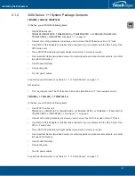
Страница 7: ...1 1 System 3200 series unit operating in conjunction with a 3200 series 1 unit and 1 1 patch panel s Note 1 1 Patch panels are only available for the TMG3200 and TSG3200 The following topics are cove...

Страница 8: ...2 and figure 1 2 on page 3 consists of One telecom unit One 1 telecom unit One or two 1 1 patch panels 1 1 3 Product Images Figure 1 1 3200 Series and 3200 Series 1 Front and Rear Views TMG3200 DS3 T...

Страница 9: ...atch Panel TE 1 1 Patch Panel DS3 1 1 Patch Panel STM1 Gateway Gateway Gateway Gateway APS Main APS Main APS Main front view rear view front view front view Gateway Gateway 1 1 Network Gateway 1 1 Net...

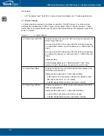
Страница 10: ...power source An IP address for the management port To avoid delays you should have the IP address netmask and gateway addresses on hand Take note that the management port supports DHCP see Section 2...

Страница 11: ...g modules Ensure that the gateways are grounded Wear an ESD preventive wrist strap and ensure that it makes good contact with your skin Connect the wrist strap clip to an unpainted surface of the equi...

Страница 12: ...nical questions TelcoBridges TB Support technical support team can be reached at the following numbers or an email can be sent to support telcobridges com Americas Europe Technical Support Centre GMT...

Страница 13: ...unting the 3200 Series Standalone or 3200 Series 1 1 System Section 2 3 Choosing your Connection Procedures Section 2 4 3200 Series Standalone System Section 2 5 3200 Series 1 1 System Section 2 6 Add...

Страница 14: ...200 TE TMG3200 DS3 or TMG3200 STM1 or TSG3200 TSG3200 TE TSG3200 DS3 or TMGIP3200 See figure 1 1 on page 2 One set of mounting brackets and screws used to mount the 3200 series unit to a 19 rack One D...

Страница 15: ...cables For patch panel information see Table 2 1 1 1 Patch Panels on page 10 Not included A 19 equipment rack The 3200 series unit must be installed on a 19 wide equipment rack TMG3200 1 TSG3200 1 TM...

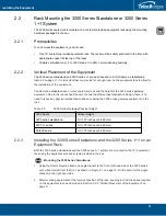
Страница 16: ...ive 1 units and the network you will required one 1 1 Patch Panel 32 T1 E1 To connect the 3200 TE 48 and the 3200 TE 64 to their respective 1 units and the network you will require two 1 1 Patch Panel...

Страница 17: ...ar exhaust heat vents and the efficient heat dissipation design there is no need to leave any physical vertical space above or below the 3200 series gateway equipment on the rack Table 2 2 3200 Series...

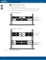
Страница 18: ...ies unit as shown in Figure 2 1 on page 12 3 Install the patch panel below the 3200 series 1 unit as shown in Figure 2 1 on page 12 Figure 2 1 Rack mounting the Equipment 3200 Series Unit 3200 Series...

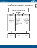
Страница 19: ...osing Your Setup 3200 Series Standalone I am setting up a 3200 Series as a standalone unit I am setting up a 3200 Series 1 1 system including a 3200 series unit 3200 series 1 and a 1 1 patch panel Go...

Страница 20: ...ll setup as a standalone system This section covers the following procedures for a 3200 series standalone system Section 2 4 1 Connecting to the 3200 Series Gateway Management Interface Section 2 4 2...

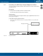
Страница 21: ...owing is needed One CAT5 Ethernet cable with RJ45 male male terminations Interconnections The 3200 series gateway provides a management interface using one gigabit Ethernet network link as shown in Fi...

Страница 22: ...Ethernet cables with RJ45 male male terminations If your system has access to a second VoIP network you can connect it to a second VoIP interface of the 3200 series gateway with an RJ45 male male CAT...

Страница 23: ...ng Your 3200 TE features SCSI connectors that in turn connect to an SCSI patch panel to terminate in RJ48C connectors for connection to T1 E1 lines You will require one patch panel for each 32 line gr...

Страница 24: ...er words they do not cross the RX and TX signals Connections between the patch panels and the 3200 series gateway require straight cables The supplied SCSI cables are straight cables Cables used to co...

Страница 25: ...he Equipment Figure 2 4 3200 TE with SCSI connectors MGMT0 ETH VOIP 0 1 0 1 TMS 0 1 16 31 0 15 16 31 0 15 SCSI patch panel 1 rear view SCSI patch panel 2 rear view SCSI patch panel front view 48 63 0...

Страница 26: ...vated by software license the number of active ports depends on the licenses purchased To connect the 3200 DS3 to the PSTN 1 Start with the Dual BNC port pair 0 right most as shown in Figure 2 5 on pa...

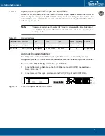
Страница 27: ...nterfaces Automatic Protection Switching The APS port is used for OC3 STM1 redundancy Switchover occurs automatically based on configurable parameters It is recommended that APS be used if the install...

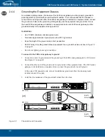
Страница 28: ...round wire with a 10 ring terminal Keep the length of the ground wire as short as possible Do NOT daisy chain the ground between equipment Use a ground bus bar as show in Figure 2 7 on page 22 Do not...

Страница 29: ...need One to two power sources 138W Two power cables for the 3200 series gateway The 3200 series gateway AC model is furnished with two AC power connectors To connect to AC Power 1 Connect an AC power...

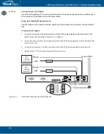
Страница 30: ...C power 1 Connect one wire from the positive terminal of the 3200 series gateway to the return side of DC power source one as shown in Figure 2 9 on page 24 2 Connect another wire from the negative te...

Страница 31: ...00 series gateway will start up and display the web portal configuration management tool Note To learn about the IP address for your system or how to change it refer to Section 3 5 Changing the 3200 S...

Страница 32: ...1 Connecting to the 3200 Series 1 1 System Management Interfaces on page 27 Section 2 5 2 Connecting to the Control Network on page 28 Section 2 5 3 Connecting the 3200 Series 1 1 System VoIP Network...

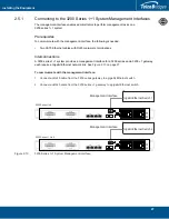
Страница 33: ...a management interface for a 3200 series and a 3200 1 gateway each require a Gigabit Ethernet network link See Figure 2 10 on page 27 To communicate with the management interface 1 Connect an RJ45 cab...

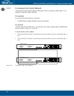
Страница 34: ...ons Connections The 3200 series unit and 3200 series 1 are connected to the control network using two CAT5 Ethernet cables as shown in Figure 2 11 on page 28 To connect to the control network 1 Connec...

Страница 35: ...witches A second one is required to support redundancy of the VoIP interface Four CAT5 Ethernet cables with RJ45 male male terminations Two IP addresses located on different subnets Connections The 32...

Страница 36: ...ng Your 3200 TE and 3200 TE 1 feature SCSI connectors that in turn connect to an SCSI patch panel to terminate in RJ48C connectors for connection to T1 E1 lines You will require one 1 1 patch panel fo...

Страница 37: ...he 1 1 patch panel must make the cross connection To connect both the 3200 TE and 3200 TE 1 SCSI to the PSTN 1 Connect each T1 E1 line from the network section of the 1 1 patch panel to the remote equ...

Страница 38: ...System Installation Guide 32 Figure 2 13 3200 TE and 3200 TE 1 connecting to the TDM 1 1 32 T1 E1 1 1 patch panel MGMT0 ETH VOIP 0 1 0 1 TMS 0 1 MGMT0 ETH VOIP 0 1 0 1 TMS 0 1 From Network 3200 TE 320...

Страница 39: ...connect both the 3200 DS3 and 3200 DS3 1 to the PSTN 1 Connect each DS3 line from the network section of the 1 1 patch panel to the remote equipment See Figure 2 14 on page 33 2 Connect each DS3 line...

Страница 40: ...patch panels and 3200 series 1 1 system Cables used to connect the network to the 1 1 patch panel must do the cross connection To connect both the 3200 STM1 and 3200 STM 1 Optical Interface to the PST...

Страница 41: ...200 STM1 and 3200 STM1 1 connecting to the STM1 1 1 patch panel MGMT0 ETH VOIP 0 1 0 1 TMS 0 1 MGMT0 ETH VOIP 0 1 0 1 TMS 0 1 Gateway Gateway APS Main APS Main APS Main 3200 Series Unit 1 1 3200 Serie...

Страница 42: ...r Guidelines Use 10 AWG minimum stranded ground wire Terminate equipment side of ground wire with a 10 ring terminal Keep the length of the ground wire as short as possible Do NOT daisy chain the grou...

Страница 43: ...s for each 3200 series unit and 3200 series 1 unit 2 5 6 1 Connecting to AC Power The 3200 series and 3200 series 1 AC models are furnished with two AC power connectors To connect to AC Power 1 Connec...

Страница 44: ...he positive terminal of the 3200 series gateway to the return side of DC power source one as shown in Figure 2 18 on page 38 2 Connect another wire from the negative terminal of the 3200 series gatewa...

Страница 45: ...3200 Series Gateway Management Port IP Address on page 55 1 Connect to the web portal http MGMT0 IP address 12358 and select the role of the unit to be part of a 1 1 redundant system Note The Welcome...

Страница 46: ...3200 Series Standalone and 3200 Series 1 1 System Installation Guide 40 3 Once you confirm the changes a progress page is displayed...

Страница 47: ...n 2 6 2 Install the 3200 Series 1 Unit on the Equipment Rack Section 2 6 3 Install a 1 1 Patch Panel Section 2 6 4 Connect to the 3200 Series 1 1 Management Interface Section 2 6 5 Connect to the 3200...

Страница 48: ...3200 Series Standalone and 3200 Series 1 1 System Installation Guide 42 3 Select a host from the Host Configuration List 4 Select the Status tab...

Страница 49: ...43 Installing the Equipment 5 Select Reset Host Role 6 Follow the instructions of the web portal to configure your unit as a primary unit in a new 3200 series 1 1 system...

Страница 50: ...TMG3200 and TSG3200 If your system features a 3200 TE TDM interface use a 1 1 patch panel 32 T1 E1 Refer to Section 2 5 4 1 SCSI Interface T1 E1 for the 3200 TE and 3200 TE 1 on page 31 Note Patch pa...

Страница 51: ...te network Follow the procedure described in Section 2 5 1 Connecting to the 3200 Series 1 1 System Management Interfaces on page 27 3200 Series Unit 3200 1 Series Unit Management Interface Gigabit Et...

Страница 52: ...he equipment rack ground bar If more than one 3200 series gateway is installed in an equipment rack each 3200 series gateway must be grounded directly to the equipment rack ground bar If your system f...

Страница 53: ...fer to Section 2 5 6 1 Connecting to AC Power on page 37 If your system operates on DC power refer to Section 2 5 6 2 Connecting to DC Power on page 38 3200 Series Unit MGMT0 ETH VOIP 0 1 0 1 TMS 0 1...

Страница 54: ...for your system or how to change it refer to Section 3 5 Changing the 3200 Series Gateway Management Port IP Address on page 55 1 Connect to the web portal of the 3200 series 1 1 system The Welcome pa...

Страница 55: ...l See Table 2 5 on page 49 Table 2 5 320000 Series Unit Displays Note An alarm will sound if one of the power supplies is faulty There is no alarm button to disable the alarm To stop the alarm you mus...

Страница 56: ...manually use the shutdown command Allow enough time for the Linux host to shut down before turning off the power to the 3200 series system example 1 minute Be aware that the shutdown procedure of the...

Страница 57: ...on 3 3 Changing 3200 Series Gateway Management Port Passwords Section 3 4 Retrieving 3200 Series Gateway Information Section 3 5 Changing the 3200 Series Gateway Management Port IP Address Section 3 3...

Страница 58: ...ust use an SSH connection The password is set at the factory and is indicated on the shipment sheet Figure 3 1 3200 Series Gateway Management Interface Note See Section 3 5 on page 55 to learn how to...

Страница 59: ...eway Note The default IP addresses for the management ports are located in the Important Notice sheet received with the shipment If you do not know the default IP address go to Section 3 5 Changing th...

Страница 60: ...Terminal Emulator Application Before communicating with the management interface you must first configure a terminal emulator or console application to communicate with the 3200 series system in orde...

Страница 61: ...retrieve the 3200 series gateway product type See http docs telcobridges com mediawiki index php TMG Get_Product_Type for further information tbserial retrieve the 3200 series gateway serial number Se...

Страница 62: ...nction with a 3200 series 1 unit refer to Section 2 5 7 Start Up on page 39 To change the default configuration of a 3200 series gateway using the Web Portal follow the steps described in the Web Port...

Страница 63: ...ps This chapter provides information about the following topics Section 4 1 Creating a Database Backup Section 4 2 Downloading a Database Backup Section 4 3 Uploading a Database Backup Section 4 4 Res...

Страница 64: ...igured Backups are performed using the web portal 4 2 Downloading a Database Backup A backup of system data is stored locally on the hard drive of the 3200 series gateway It is important that system b...

Страница 65: ...59 Appendix A Wiring Diagrams...

Страница 66: ...t Connected RJ 48 T1 E1 J1 Wiring Schematic Crossover Cable 1 8 RX Ring 1 RX Tip 2 Not Connected 3 TX Ring 4 TX Tip 5 Not Connected 6 Not Connected 7 Not Connected 8 1 RX Ring 2 RX Tip 3 Not Connected...

Страница 67: ...61 Wiring Diagrams A 2 Tmedia Serial Adapter Wiring Diagram 1 N C 2 Rx 3 Tx 4 N C 5 GND 6 N C 7 N C 8 N C 9 N C 1 N C 2 N C 3 N C 4 GND 5 Tx 6 Rx 7 N C 8 N C DB 9 RJ 45 2 3 5 1 8...

Страница 68: ...3200 Series Standalone and 3200 Series 1 1 System Installation Guide 62...

Отзывы: