


Theory of Operation
3–14
SPG 422 Service Manual (B034000 and above)
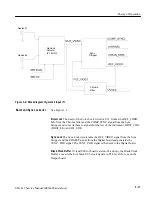
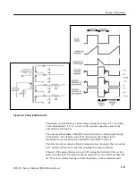
The clock and reset drive the counter chain. The first counter in the chain is the
horizontal counter. This 11-bit up-counter counts at 27 MHz and resets itself at
the end of the video line. It is also reset by the frame reset input, either
(BLKFRN0) or (BLKFRP0). The line length is specified by the video standard
selected. On the last count of the line, the counter issues a horizontal carry pulse.
The horizontal segment decoder is implemented in a state machine. This state
machine uses the outputs of the horizontal counter and some special timing
control signals from the horizontal counter. The horizontal segment data is used
to divide the horizontal line into a small number of unique regions. This allows
the storage of the actual signal data to be dramatically compressed.
The second counter in the chain is the vertical counter. This is a 10-bit up-count-
er that runs at 27 MHz. However, it is only enabled to count once per video line
by the horizontal carry pulse. It counts to the end of the frame in the selected
video standard and then resets itself. (It is also reset by the frame reset input.) On
the last count of the frame, the counter issues a vertical carry pulse.
The third counter in the chain is the frame counter. It is a 2-bit up-counter that
runs at 27 MHz. However, it is only enabled to count once per video frame by
the horizontal and vertical carry pulses. It counts to the end of the color frame in
the selected video standard and then resets itself. (It is also reset by the frame
reset input.)
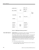
Segment Decoder PROMs.
The counters, the horizontal segment decoder, and the
signal selection bits from the processor drive the segment decoder PROMs.
There is one PROM for NTSC, U38, and two (to get the required output bus
width) for PAL, U36 and U37. These PROMs decode the counter and decoder
inputs into pointers to unique blocks of eight samples of black burst data.
Signal Segment Data PROMs.
The signal segment data PROMs, U39 and U40
(which are time-multiplexed to double the speed), take the segment pointers
from the decoder PROMs and output the 8-bit black burst data.
DAC and Output Filter.
The DAC, U32, and output circuitry convert the digital
representation of black burst to analog, reconstruct the signal, filter it, and buffer
it to drive 75
W
.
Содержание SPG 422
Страница 4: ......
Страница 14: ...Service Safety Summary x SPG 422 Service Manual B034000 and above ...
Страница 17: ......
Страница 61: ...Specifications 1 44 SPG 422 Service Manual B034000 and above Figure 1 48 Pluge CB and CR channels ...
Страница 62: ......
Страница 67: ......
Страница 92: ......
Страница 96: ...Performance Verification 4 4 SPG 422 Service Manual B034000 and above ...
Страница 102: ...Performance Verification 4 10 SPG 422 Service Manual B034000 and above ...
Страница 136: ...Performance Verification 4 44 SPG 422 Service Manual B034000 and above ...
Страница 137: ......
Страница 144: ......
Страница 158: ...Maintenance 6 14 SPG 422 Service Manual B034000 and above ...
Страница 159: ......
Страница 162: ......
Страница 223: ...9 3 SPG 422 Service Manual SPG 422 Component Digital Sync Generator FRONT PANEL 1 ...
Страница 224: ...SPG 422 Service Manual 9 4 ...
Страница 226: ...SPG 422 Service Manual 9 6 A2 Digital Board Static Sensitive Devices See Maintenance Section ...
Страница 227: ...9 7 SPG 422 Service Manual SPG 422 Component Digital Sync Generator CPU 1 ...
Страница 228: ...SPG 422 Service Manual 9 8 A7 Serial Filter ...
Страница 229: ...9 9 SPG 422 Service Manual SPG 422 Component Digital Sync Generator CPU I O 2 ...
Страница 230: ...SPG 422 Service Manual 9 10 ...
Страница 232: ...SPG 422 Service Manual 9 12 ...
Страница 233: ...9 13 SPG 422 Service Manual 54 31 7 54 31 7 0 2 7 2 7 2 7 0 8698707 313 5 7 070 8 SERIAL COPROCESSORS 4 ...
Страница 234: ...SPG 422 Service Manual 9 14 ...
Страница 236: ...SPG 422 Service Manual 9 16 ...
Страница 237: ...9 17 SPG 422 Service Manual SPG 422 Component Digital Sync Generator 13 5 MHz GENLOCK CONTROL 6 ...
Страница 238: ...SPG 422 Service Manual 9 18 ...
Страница 239: ...9 19 SPG 422 Service Manual SPG 422 Component Digital Sync Generator 108 MHz OSCILLATOR 7 ...
Страница 240: ...SPG 422 Service Manual 9 20 ...
Страница 241: ...9 21 SPG 422 Service Manual SPG 422 Component Digital Sync Generator FINE PHASE 8 ...
Страница 242: ...SPG 422 Service Manual 9 22 ...
Страница 244: ...SPG 422 Service Manual 9 24 ...
Страница 248: ...SPG 422 Service Manual 9 28 A3 Output Board Back Static Sensitive Devices See Maintenance Section 671 3123 02 and above ...
Страница 250: ...SPG 422 Service Manual 9 30 ...
Страница 252: ...SPG 422 Service Manual 9 32 ...
Страница 254: ...SPG 422 Service Manual 9 34 ...
Страница 256: ...SPG 422 Service Manual 9 36 ...
Страница 258: ...SPG 422 Service Manual 9 38 ...
Страница 260: ...SPG 422 Service Manual 9 40 ...
Страница 264: ...SPG 422 Service Manual 9 44 ...
Страница 265: ...9 45 SPG 422 Service Manual 53654 48 1018 2 94 4 7 857 PART OF A5 OPTION 1 BOARD ...
Страница 266: ...SPG 422 Service Manual 9 46 ...
Страница 268: ...SPG 422 Service Manual 9 48 ...
Страница 270: ...SPG 422 Service Manual 9 50 ...
Страница 274: ...SPG 422 Service Manual 9 54 ...
Страница 276: ...SPG 422 Service Manual 9 56 ...
Страница 277: ......
Страница 278: ......
Страница 285: ...10 7 SPG 422 Service Manual A2 A3 A4 A2A1 A5 A6 A7 A8 A1 Fig 1 Exploded view SPG 422 Component Digital Sync Generator ...
Страница 286: ...SPG 422 Service Manual 10 8 ...


