background image

Reference

Serial Mask Testing & Serial Pattern Trigger User Manual

15

Overview

Related control elements and resources

To mask test a waveform (cont.)

Enable and set

waveform

autofit

parameters

10.

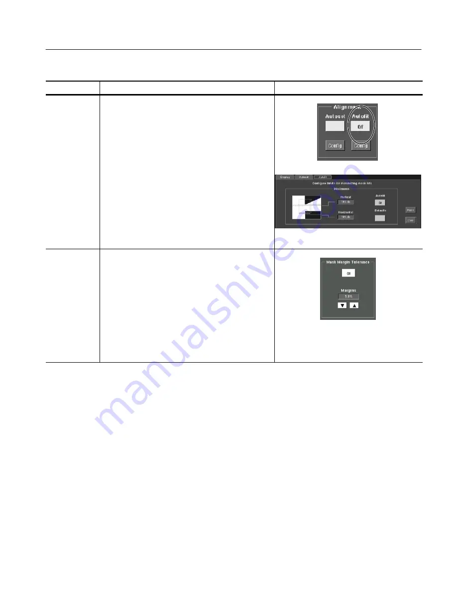
In the Masks tab, touch the Autofit button to enable the
waveform autofit function. Autofit checks each waveform
for any mask hits. If there are hits, autofit repositions the
waveform to minimize hits. The number of hits reported
is the number after autofit has minimized hits.

The autofit Config button lets you set the autofit
maximum waveform repositioning parameters (as a
percentage of the horizontal and vertical divisions),
return to default settings, or return to the Mask Setup
control window. Use the keypad to change the vertical or
horizontal autofit parameters.

11.

Touch the Masks button to return to the Mask control
window.

Set mask test

tolerance

margins

12.

Touch the Masks Setup window Tolerance tab to set the
percentage of margin used in the mask test. Use the
control knob, keypad, pop-up keypad, or up and down
arrow buttons to enter the mask margin tolerance
percentage. The range of values is --50% to 50%.

Margin tolerance settings greater than 0% expand the
size of the segments, making the mask test harder to
pass; margin tolerance settings less than 0% (negative
percent) reduces the size of the segments, making the
mask test easier to pass.

Содержание CSA7000 Series

Страница 1: ...Series Serial Mask Testing Serial Pattern Trigger TDS6000 TDS7000 Series Option SM Serial Mask Testing Option ST Serial Pattern Trigger 071 1035 03 This document applies to firmware version 2 2 and above www tektronix com ...

Страница 2: ...nd foreign patents issued and pending Information in this publication supercedes that in all previously published material Specifications and price change privileges reserved Tektronix Inc P O Box 500 Beaverton OR 97077 0001 TEKTRONIX and TEK are registered trademarks of Tektronix Inc ...

Страница 3: ...unctions on TDS6000 and TDS7000 Series Instruments 3 Operating Basics 5 Serial Mask Testing Functions 5 Accessing Serial Pattern Trigger Functions 8 Reference 11 Mask Testing 11 Communication Comm Triggering 32 Serial Pattern Trigger 36 Appendix A Supported Mask Types and Standards 41 Appendix B Supported Communication Trigger Codes and Standards 45 Appendix C Automatic Communication Signal Measur...

Страница 4: ...le 6 Ethernet masks 41 Table 7 SONET SDH masks 42 Table 8 Fibre Channel masks 42 Table 9 Fibre Channel Electrical masks 42 Table 10 InfiniBand masks 42 Table 11 Serial ATA masks 42 Table 12 USB 1 1 2 0 masks 43 Table 13 1394b masks 43 Table 14 Rapid IO LP LVDS masks 43 Table 15 Rapid IO Serial masks 43 Table 16 IOF masks 44 Table 17 PCI Express masks 44 Table 18 AMI trigger standards 45 Table 19 B...

Страница 5: ...on TDS6000 and TDS7000 instruments H Explains how to access and operate the features Manual Structure This manual is organized into the following chapters H Getting Started provides an overview of the Serial Mask Testing and Serial Pattern Trigger functions and shows you how to install these functions on TDS6000 and TDS7000 instruments H Operating Basics describes how to access the functions using...

Страница 6: ...rument and how they operate User Manual1 The user manual for the CSA7000 TDS7000 and TDS6000 instruments Programmer Online Guide An alphabetical listing of the programming commands and other information related to controlling the instrument over the GPIB and TekVISA interfaces Service Manual A description of how to service the instrument to the module level This optional manual must be ordered sep...

Страница 7: ...ktronix com Sales support 1 800 833 9200 select option 1 Service support 1 800 833 9200 select option 2 Technical support Email techsupport tektronix com 1 800 833 9200 select option 3 6 00 a m 5 00 p m Pacific time This phone number is toll free in North America After office hours please leave a voice mail message Outside North America contact a Tektronix sales office or distributor see the Tektr...

Страница 8: ...Preface vi Serial Mask Testing Serial Pattern Trigger User Manual ...

Страница 9: ...ion detection and pass fail testing Signal violation detection lets you test communications signals for time or amplitude violations against a predefined mask Each mask consists of one or more polygonal regions called segments The signal waveform data should stay outside of the segments defined by the mask Any signal data that occurs inside a mask segment is called a mask segment violation or hit ...

Страница 10: ...alling user defined masks H Waveform database technology to do mask testing based on waveforms accumulated in a database rather than a single waveform stored in acquisi tion memory H Communications triggers to trigger the instrument on industry standard communications signals H Automatic measurements on communications signals H Clock recovery from the serial data stream except for TDS7104 and TDS7...

Страница 11: ...attern Trigger Functions on TDS6000 and TDS7000 Series Instruments To enable the optional Serial Mask Testing and or Serial Triggering functions on TDS6000 and TDS7000 instruments you must have a valid Option Installation Key Do the following steps 1 From the oscilloscope menu bar touch the Utilities menu select Option Installation and then touch Continue 2 Enter the authorization key using the in...

Страница 12: ...Getting Started 4 Serial Mask Testing Serial Pattern Trigger User Manual ...

Страница 13: ...c communication signal measurements This section describes how to access these functions To access the Serial Mask Test functions touch the Masks tool bar button The instrument displays the Masks control window as shown in Figure 1 Figure 1 Masks control window Table 1 describes the Masks control window tab functions Refer to the Reference chapter beginning on page 11 of this manual as well as the...

Страница 14: ...ns as shown in Figure 2 Figure 2 Communication signal trigger functions Table 2 describes the communication trigger functions Refer to the Reference chapter beginning on page 11 of this manual as well as the online help for more information about these functions Table 2 Communication trigger functions Menu Function Source Sets the waveform data source Ch1 Ch4 Type Sets the waveform source type Dat...

Страница 15: ...n the selected code and standard Pulse Form Sets the comm signal pulse format on which to trigger this function is displayed when required by a selected standard Serial Mask Testing uses the built in automatic communications measurements To access the communications signal automatic measurements do the following steps 1 Touch the Meas tool bar button The instrument displays the Measurement control...

Страница 16: ... more information about these functions Table 3 Serial trigger functions Menu Function Data Src Sets the serial trigger waveform data source Ch1 Ch4 Clk Src Sets the serial trigger clock source Ch1 Ch4 Recovered Clock the recovered clock function is not available on the TDS7104 or the TDS7054 and is only available for NRZ coded signals on the TDS6000 and TDS7000 Series instruments Clk Polarity Set...

Страница 17: ...igger User Manual 9 Table 3 Serial trigger functions cont Menu Function Editor Opens the serial pattern data editor which lets you define the serial pattern on which to trigger Format Displays the serial trigger pattern data in binary or hexadecimal format ...

Страница 18: ...Operating Basics 10 Serial Mask Testing Serial Pattern Trigger User Manual ...

Страница 19: ...ern Trigger page 36 describes how to trigger on user defined serial data Mask Testing Mask testing sets the instrument to test industry standard communications signals against defined masks to verify the timing amplitude and waveform shape of the signal This section provides step by step instructions on how to access and operate the mask test features The mask testing instructions cover the follow...

Страница 20: ...instrument to the source signal or save the source signal to a math or reference waveform memory location Access the Mask Setup window 2 From the button bar touch Masks The instrument displays the Mask control window Select a mask test signal source 3 Select the Source tab and then the channel math or reference tab and then select the waveform source to use as the mask test source You can mask tes...

Страница 21: ...t align the signal in the mask adjust the instrument vertical and horizontal controls If you touch the Autoset button and the Autoset Undo preference is On the instrument will display an Autoset Undo window Touch the Undo button to return to the previous settings or touch the Close button to remove the window Select the mask standard 5 To specify the mask standard select a standard from the drop d...

Страница 22: ... 9 In the Masks tab touch the Autoset button to have the instrument automatically adjust instrument settings to align the waveform to the mask based on the characteristics of the input signal Autoset is done on the first waveform acquired after touching the Autoset button If the Autoset Undo preference is On the instrument will display an Autoset Undo window Touch the Undo button to return to the ...

Страница 23: ...centage of the horizontal and vertical divisions return to default settings or return to the Mask Setup control window Use the keypad to change the vertical or horizontal autofit parameters 11 Touch the Masks button to return to the Mask control window Set mask test tolerance margins 12 Touch the Masks Setup window Tolerance tab to set the percentage of margin used in the mask test Use the control...

Страница 24: ...test fails have the instrument beep BEEP send an SRQ out on the GPIB bus SRQ send a trigger pulse out on the AUX OUT connector AUX Out stop signal acquisition immediately Stop Acq and or print the instrument screen image to a printer Print 16 Touching the More button displays more failure functions Save Wfm saves the the waveform data of the first waveform that causes the test to fail to a wfm fil...

Страница 25: ...buttons to set mask and waveform polarity Positive tests the positive waveform pulses Negative inverts the mask and tests the negative waveform pulses Both tests the first half of the tested waveforms in positive polarity mode then tests the remaining waveforms in negative polarity mode 19 Toggle the Repeat button to On to set the instrument to repeat continue mask testing on the completion of eac...

Страница 26: ... turn on mask pass fail testing You can touch Reset prior to running tests to clear the Pass Fail Test Summary fields You can also use the Pass Fail Test button in the Pass Fail Setup control window The instrument begins mask testing and displays the test summary information in the Pass Fail Test Summary fields If a mask has more than three segments the window displays a horizontal scroll bar belo...

Страница 27: ... window 1 From the button bar touch Masks and select the Masks tab The instrument displays the Mask control window Select the mask type and standard 2 Touch the appropriate button in the Type field to select a mask type Touch the More button to display further selections 3 Select a standard from the drop down list The control window lists mask types and standards that are available on your instrum...

Страница 28: ...rument copies the current mask to the user mask memory Edit the user mask 6 Refer to Editing a User Mask on page 21 Save the user mask to disk 7 Refer to Saving a User Mask to Disk on page 23 You do not need to save the edited user mask to disk as the instrument retains the current user mask in nonvolatile memory However if you plan on creating a number of user masks you will need to store the use...

Страница 29: ... Controls button to open the mask edit controls window on the right side of the screen This provides the maximum area to display the mask making editing easier Select a segment 5 Touch the Segment field and use the arrow buttons multipurpose knob or keypad to select a segment to edit The selected active segment is highlighted in red Each mask can have up to 16 segments Select a vertex 6 Touch the ...

Страница 30: ...hange the selected vertex vertical position Add or delete a vertex 9 To add a vertex select the closest vertex that is clockwise from where you want to place a new vertex Touch Add to add a vertex midway between the selected vertex and the next counter clockwise vertex 10 To delete a vertex enter or select the vertex number Then touch Delete to delete the selected vertex The remaining vertices loc...

Страница 31: ...ouch Masks and select the Masks tab 2 Touch the User Mask button 3 Touch the Edit User Mask button The instrument displays the Mask Edit control window Save the user mask to disk 4 Touch the Mask Save button The instrument opens the Save Mask As dialog The default save location is in the TekScope Masks folder 5 Enter the mask name in the File Name field The default save type is User Mask Files msk...

Страница 32: ...User Mask button 3 Touch the Edit User Mask button The instrument displays the Mask Edit control window Recall the user mask from disk 4 Touch the Mask Recall button The instrument opens the Recall Mask dialog The default recall location is the TekScope Masks folder If the mask files are in another folder use the navigation controls to access the appropriate folder 5 Select the mask name 6 Touch R...

Страница 33: ...ttings with the mask information See the instrument user manual for information on displaying waveforms Create an empty user mask 2 From the button bar touch Masks and select the Masks tab 3 Touch the User Mask button 4 Touch the mask standard field to display the drop down list 5 Select None from the list 6 Touch the Copy Current Mask to User Mask button If you are asked if you want to overwrite ...

Страница 34: ...ield and use the arrow buttons multipurpose knob or keypad to enter or select segment 1 10 Touch the Vertex Add button The instrument draws the default new segment shape a triangle 11 Use the instructions in Editing a User Mask starting at step 5 on page 21 to edit a segment 12 Repeat steps 9 through 11 selecting an unused and sequential segment number to create and edit more segments Save the use...

Страница 35: ...nnect your DS1A signal to CH 1 through suitable cables probes or adapters 2 Press DEFAULT SETUP CSA7000 Instrument Signal Source Output Set instrument settings 3 From the button bar touch Masks and select the Masks tab 4 Touch the ANSI T1 102 button If not using an DS1A signal touch the button appropriate for the signal that you are using 5 Touch the mask standard field to display the drop down li...

Страница 36: ...ssumes that the autoset undo preference is off or that you touch Close to close the Autoset Undo control window Select the source 8 In this example we are using the default source CH 1 Change the tolerance 9 Set the Mask Margin Tolerance to the percentage of margin used in the mask test this example uses the default OFF H OFF to test the signal to the selected mask standard H Settings greater than...

Страница 37: ...urrent test is passing H Pass Fail Test Summary displays the number of samples waveforms tested the total number of hits failures and settings that you selected for the test H Hits per segment displays the number of hits in each segment of the mask H Pass Fail Test allows you to reset the test and to turn the test on and off Triggers set automatically 12 When you turn on masks the instrument autom...

Страница 38: ...verlap The number of mask hits is the sum of all hits in all segments regardless of whether or not segments overlap For example if a waveform crosses over an area where two segments overlap both segments will count the waveform hit Vertices Each segment can have a maximum of 50 vertices Vertices are numbered counterclockwise with vertex one generally located at the bottom left of each segment The ...

Страница 39: ... E Electrical Out to Ch1 Input Adapter are calibrated optical reference receivers This means that the instrument optical to electrical converter and instrument input channel have been tuned to have a fourth order Bessel Thompson response as well as the correct frequency response for each supported standard by use of digital filters H When the O E Electrical Out to Ch1 Input Adapter is installed yo...

Страница 40: ...cation signals do the following procedure Overview Communication triggering Related control elements and resources Access the trigger control window 1 From the button bar touch Trig and select the A Event trigger tab The instrument opens the Trigger Setup control window Select a com munications trigger 2 Touch the Comm button The instrument displays the Comm Trigger controls Select comm trigger so...

Страница 41: ... multipurpose knob or keypad to enter the serial data stream bit rate for nonstandard bit rates Note Changing the bit rate means the instrument is not triggering in accordance with the standard The Standard type changes to Custom when you change the bit rate value Select comm trigger type 7 Touch the Type button to select the signal type Select from Data Clock and R Clk recovered clock Recovered c...

Страница 42: ...form button to select a pulse form setting where each button means AMI Isolated 1 Isolated 1 and eye diagram CMI 1 binary 1 0 binary zero 1 inverse of binary 1 and eye diagram NRZ and MLT3 eye diagram only no buttons displayed Select comm trigger threshold levels 10 Depending on the code and standard setting the instrument displays the Clock Level field with one or two threshold fields Touch each ...

Страница 43: ...b s are also available at the front panel of a CSA7000 Series instrument H When you select recovered clock the instrument attempts to trigger on and acquire a lock on the derived clock signal If the source data stream is interrupted or is very distorted then the instrument may not acquire a lock or may loose signal lock causing an unstable waveform display If this occurs verify that the source sig...

Страница 44: ...is not available on TDS7054 or TDS7104 instru ments To set the instrument to trigger on a user defined serial data stream do the following procedure Overview Serial trigger setup Related control elements and resources Access the trigger control window 1 From the button bar touch Trig and select the A Event trigger tab The instrument opens the Trigger Setup control window Select serial trigger 2 To...

Страница 45: ...erial data stream data threshold level Select serial trigger coding and standard 5 The Coding button always shows NRZ code type 6 Touch the Standard button and select the appropriate standard from the list The standard selected determines the bit rate 7 The Bit Rate field shows the bit rate for the selected standard Touch the Bit Rate field and use the multipurpose knob or keypad to enter the seri...

Страница 46: ...r information on the Recovered Clock function 9 If the clock source is different than the data source except for R Clk the instrument displays the Clk Polarity button and the Clk Level field Touch Clk Polarity to set the clock signal polarity to Pos itive or Neg ative Touch the Clk Level field and use the arrow buttons multipurpose knob or keypad to enter the clock signal threshold level View the ...

Страница 47: ... also use the mouse or the keyboard arrow keys to move the insertion cursor 15 Touch the Backspace button to erase the character to the left of the insertion cursor 16 Touch the Clear button to erase all pattern data from the pattern field 17 Touch the appropriate keypad character to enter a character You can also use the keyboard to enter binary or hexadecimal characters You can enter a maximum o...

Страница 48: ...Reference 40 Serial Mask Testing Serial Pattern Trigger User Manual ...

Страница 49: ...s E1 Coax Pair 2 048 Mb s E2 8 448 Mb s E3 34 368 Mb s E4 Binary 0 139 26 Mb s E4 Binary 1 139 26 Mb s STM1E Binary 0 155 52 Mb s STM1E Binary 1 155 52 Mb s Table 5 ANSI T1 102 masks None DS1 1 544 Mb s DS1A 2 048 Mb s DS1C 3 152 Mb s DS2 6 312 Mb s DS3 44 736 Mb s DS4NA 139 26 Mb s DS4NA Max Output 139 26 Mb s STS 1 Pulse 51 84 Mb s STS 1 Eye 51 84 Mb s STS 3 155 52 Mb s STS 3 Max Output 155 52 M...

Страница 50: ...266E Elec 265 6 Mb s FC531E Elec 531 2 Mb s FC1063E Elec 1 0625 Gb s FC1063E Norm Beta Transm FC1063E Norm Delta Transm FC1063E Norm Gamma Transm FC1063E Abs Beta Transm FC1063E Abs Delta Transm FC1063E Abs Gamma Transm FC1063E Abs Beta Recv FC1063E Abs Delta Recv FC1063E Abs Gamma Recv FC2125E Norm Beta Transm FC2125E Norm Delta Transm FC2125E Norm Gamma Trans FC2125E Abs Beta Transm FC2125E Abs ...

Страница 51: ...00β Optical 491 5 Mb s S800b T1 983 0 Mb s S800b T2 983 0 Mb s S800β Optical 983 0 Mb s S1600b T1 1 966 Gb s S1600b T2 1 966 Gb s S1600β Optical 1 966 Gb s Table 14 Rapid IO LP LVDS masks None Drv 500 Mb s Drv 750 Mb s Drv 1 0 Gb s Drv 1 5 Gb s Drv 2 0 Gb s Ext Drv 500 Mb s Ext Drv 750 Mb s Ext Drv 1 0 Gb s Ext Drv 1 5 Gb s Ext Drv 2 0 Gb s Rcv 500 Mb s Rcv 750 Mb s Rcv 1 0 Gb s Rcv 1 5 Gb s Rcv 2...

Страница 52: ... SFI SPI 5 RD Data 2 488 Gb s SFI SPI 5 RB Clock 2 488 Gb s SFI SPI 5 RD Clock 2 488 Gb s SFI SPI 5 TA Data 3 125 Gb s SFI SPI 5 TC Data 3 125 Gb s SFI SPI 5 TA Clock 3 125 Gb s SFI SPI 5 TC Clock 3 125 Gb s SFI SPI 5 RB Data 3 125 Gb s SFI SPI 5 RD Data 3 125 Gb s SFI SPI 5 RB Clock 3 125 Gb s SFI SPI 5 RD Clock 3 125 Gb s VSR OC192 STM64 1 24416 Gb s TFI 5 2 488 Gb s TFI 5 3 1104 Gb s Table 17 P...

Страница 53: ...the bandwidth and or configuration of that instrument Table 18 AMI trigger standards Custom 32Mb 32 064 Mb s 97Mb 97 728 Mb s DS1 1 544 Mb s DS1A 2 048 Mb s DS1C 3 152 Mb s DS2 6 312 Mb s DS2 Rate Sym 6 312 Mb s DS2 Rate Coax 6 312 Mb s DS3 44 736 Mb s E1 2 048 Mb s E2 8 448 Mb s E3 34 368 Mb s STS 1 51 84 Mb s Table 19 B3ZS trigger standards Custom DS3 44 736 Mb s STS 1 51 84 Mb s Table 20 B6ZS t...

Страница 54: ...C266 265 6 Mb s FC531 531 2 Mb s FC1063 1 0625 Gb s FC2125E 2 125 Gb s G1 ATA 1 5 Gb s G2 ATA 3 0 Gb s TDS6000 only G3 ATA 6 0 Gb s TDS6000 only GB Ethernet 1 25 Gb s FS USB 12 Mb s HS USB 480 Mb s OC1 STM0 51 84 Mb s OC3 STM1 155 5 Mb s OC12 STM4 622 1 Mb s OC48 STM16 2 488 Gb s OC48 FEC 2 666 Gb s S400b 491 5 Mb s S800b 983 0 Mb s S1600b 1 966 Gb s XAUI 3 125 Gb s RapidIO 500M 500 Mb s RapidIO 7...

Страница 55: ...e Width TCross2mean 3 TCross2sigma TCross1mean 3 TCross1sigma Crossing The eye crossing point as a percentage of eye height Crossing 100 PCross1mean PBasemean PTopmean PBasemean Eye Top The top of the eye Eye Base The base of the eye Jitter Pk Pk The peak to peak value for the edge jitter in the current horizontal units p p g j Jitter PP TCross1PP Jitter RMS The RMS value of the edge jitter in the...

Страница 56: ... of the eye period DCD sec 100 x TDCDp p TCross2mean TCross2mean Quality Factor Ratio of eye size to noise y y Quality Factor PTopmean PBasemean PTopsigma PBasesigma Levels Used in Taking Eye Measurements All eye diagram measurements are based on the power level the voltage level or the time locations of edges within each acquisition Figure 5 shows an eye diagram and the areas from which values ar...

Страница 57: ...wing directions H TCross1mean the horizontal mean of the left crossing point at TCross1 H TCross1sigma the horizontal standard deviation of the left crossing point at TCross1 H TCross1pk pk the horizontal peak to peak deviation of the left crossing point at TCross1 H PCross1mean the vertical mean of the left crossing point at PCross1 The T2 values are vertical and horizontal values associated with...

Страница 58: ...Appendix C Automatic Communication Signal Measurements 50 Serial Mask Testing Serial Pattern Trigger User Manual ...

Страница 59: ...ern 39 format 38 functions 6 hexadecimal format 38 39 key points 35 level 38 mask testing 25 phase lock loop 35 polarity 38 pulse form 34 recovered clock 33 35 38 recovered clock key points 35 selecting 32 selecting a code 37 selecting a data source 37 selecting a source 32 selecting a standard 33 37 selecting a trigger 36 selecting a type 33 serial data 37 serial data pattern 39 serial pattern da...

Страница 60: ...ument settings 27 interactions 30 key points 30 key points optical 31 log date 16 margin tolerance 15 30 margins 15 30 mask hits 30 mask type 13 masks directory 24 moving a mask vertex 22 negative polarity 17 number of waveforms to test 16 O E out to CH1 adapter 31 optical 31 pass and fail parameters 16 polarity 17 positive polarity 17 print 16 recall mask dialog 24 recalling a user mask from disk...

Страница 61: ...48 Measurements 47 eye measurement levels 48 levels used in taking 48 reference levels defined eye pattern optical 49 supported 47 N Noise Pk Pk measurement 47 Noise RMS 47 P Phone number Tektronix v Preface iii Product description 1 Product support contact information v Q Q Factor 48 Quality Factor 48 R Recovered clock 31 33 35 38 key points 35 Reference 11 Reference receivers 31 Related manuals ...

Страница 62: ...Index 54 Serial Mask Testing Serial Pattern Trigger User Manual ...

Отзывы: