C
L E A R
P
A T H
M C / S D
U
S E R
M
A N U A L
R
E V
.
3 . 0 9
3 0
T
EKNIC
,
I
NC
. T
EL
.
(585)
784-7454
O
VERVIEW
:
C
LEAR
P
ATH
I/O
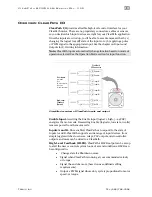
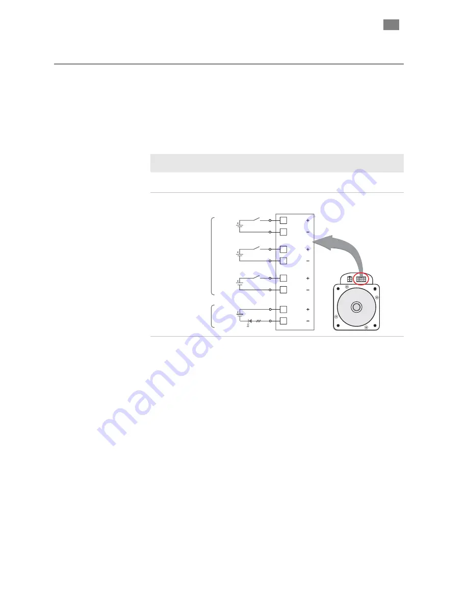
ClearPath I/O
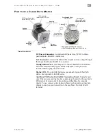
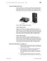
provides a flexible high-level control interface for your
ClearPath motor. There are no proprietary connectors, cables or sensors,
so you decide which input devices are right for your ClearPath application.
Once the inputs are wired up, you’ll be able to execute moves either by 1)
changing the logical (on/off) state of the inputs or 2) by applying a pulse
or PWM signal to the appropriate input. See the chapter on
Inputs and
Outputs
for I/O wiring information.
Note:
ClearPath inputs automatically change function based on mode of
operation selected. See the Operation Mode section for input function.
1
5
4
8
3
7
2
6
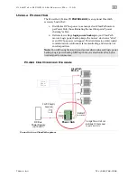
Enable
Enable
Input A
Input A
Input B
Input B
HLFB
HLFB
5-24VDC
5-24VDC
5-24VDC
5-24VDC
User Inputs
• Switches
• PLC
• Micro-controller
• Sensors
• Signal generator
High-Level
Feedback
(Output)
ClearPath
I/O Connector
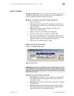
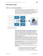
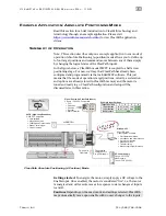
Simplified overview of ClearPath inputs and output
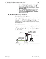
Enable Input.
Asserting the Enable input
(logical 1, high, 5–24VDC)
energizes the motor coils. Deasserting Enable (logical 0, low state, 0 volts)
removes power from the motor coils.
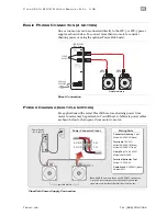
Inputs A and B.
Once enabled, ClearPath can respond to the state of
Inputs A and B. ClearPath supports a wide range of input devices, from
simple toggle switches to sensors, relays, PLC outputs, microcontroller
outputs, and more can be wired to a ClearPath.
High-Level Feedback (HLFB).
ClearPath’s HLFB output can be set up
to alert the user or control system to one of several conditions. HLFB can
be configured to:
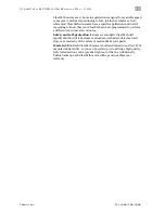
•
Change state if a Shutdown occurs.
•
Signal when ClearPath is running at your commanded velocity
or torque.
•
Signal the end of a move (based on user-defined settling
requirements).
•
Output a PWM signal whose duty cycle is proportional to motor
speed, or torque.

