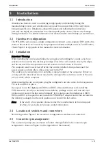
Figure 2.
Pin layout on D-Sub 25 (male), D-Sub 9 (male) and header type connectors
(2x 5 pins, 2.54 mm pitch).
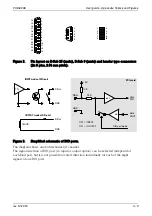
Figure 3.
Simplified schematic of DIO ports.
The diagram shows one bidirectional I/O channel.
The signal direction of DIO port (ie. input or output option) can be selected independ for
each 8-bit port, but it is not possible to select direction individually for each of the eight
signals of one DIO port.
PCD-8006
User guide - Appendix, Tables and Figures
rev. 10.2015
II - 3
5
4
3
2
1
6
7
8
9
10
11
12
13
14
15
16
17
18
19
20
21
22
23
24
25
8
7
6
5
4
3
2
1
9
1
2
9
10
3
5
7
4
6
8
10K
GND
+5V
TTL
DIOxx
33R
DIO port mode
=> INPUT
ON
OFF
=> OUTPUT
INPUT mode of DIO port
>500R
OUTPUT mode of DIO port
data
DIN
data
DOUT
PCIe card
DIOxx
DIOxx
GND
GND
HCT
HC
Содержание PCD-8006
Страница 1: ...Digital I O PCIe card PCD 8006 User Guide ...
Страница 12: ... PCD 8006 User Guide Notes ...
Страница 13: ......
Страница 14: ......


