54
SERVICE HANDBOOK
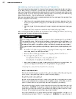
Step 1: Before Continuing with Troubleshooting…
WARNING! All electric power should be disconnected and you should have already made
sure that the compressor does not have a ground fault (see “Checking for a Ground Fault”
on pages 40-41). You should have also checked the windings for continuity and proper
resistance (see “Checking for Continuity and Proper Resistance” on page 42), made sure
the system is getting proper voltage, and that the control, thermostat, and contactor are
working properly.
Step 2: Disconnect Fan Motor or Any Other Devices
If there is a fan motor or any other auxiliary device, open the circuit for the fan motor or any
other device.
Step 3: Check External Thermal Protector
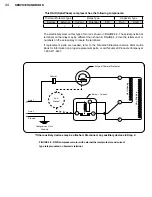
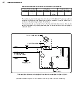
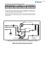
Check for continuity across the thermal protector (line 1 and compressor terminal con-
nection). If there is no continuity then the thermal protector may be tripped. Wait for the
protector to cool off and close. This may take more than an hour. Check continuity gain.
If there is no continuity, replace the protector.
Step 4: Check Protector Wiring
Confirm that there is continuity between:
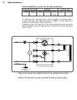
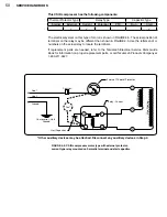
The power input terminal on the thermal protector and 5 on relay.
The protector common lead wire and C.
Step 5: Check Potential Relay
Before checking the relay, be sure it is mounted at the proper position (see pages 28-32).
Check the potential relay by measuring continuity between:
•
Relay terminals 5 and 2. If there is no continuity, replace the relay.
•
Relay terminals 2 and 1. If there is no continuity, then the contact are open. Replace
the relay.
Possible reasons that a relay is not working properly include:
•
Use of incorrect relay.
Replace with correct relay.
•
Line voltage is too high or low (greater than 100% or less than 90% of rated volt-
age).
•
Excessive short cycling.
Short cycling can be caused by problems with the com-
pressor’s thermal protector or system components such as the thermostat, control,
contactor, or high or low pressure cut-out. For more information on troubleshooting
the thermal protector, see Step 3. For troubleshooting the system components, refer
to the OEM service information.
•
Vibration due to loose relay mounting.
Tighten relay mounting.
•
Use of incorrect run capacitor.
Replace with proper run capacitor.
Содержание AH5540E
Страница 1: ...Hermetic Compressor Service Handbook Wholesale Distribution North America...
Страница 2: ......
Страница 3: ...Hermetic Compressor Service Handbook Ann Arbor MI 48108 REV 3 11...
Страница 4: ......
Страница 8: ......
Страница 9: ...Chapter 1 General Service Safety Precautions...
Страница 16: ......
Страница 17: ...Chapter 2 Model and Application...
Страница 22: ......
Страница 23: ...Chapter 3 Compressor Motor and Component...
Страница 36: ......
Страница 37: ...Chapter 4 Servicing...
Страница 38: ...30 SERVICE HANDBOOK...
Страница 79: ...71...
Страница 80: ......
Страница 81: ...Chapter 5 Installation and Replacement...
Страница 96: ......
Страница 97: ...Liquid refrigerant migration to compressor FIGURE 6 1 Chapter 6 Operation...
Страница 108: ......
Страница 109: ...Appendix...
Страница 113: ...105 Reciprocating Compressor FIGURE A 2 Internal view of typical air conditioning compressor...
Страница 118: ...110 SERVICE HANDBOOK Notes...
Страница 119: ......

