operates with ISO9001 certified quality system
http://www.tecsystem.it
R. 1.1 29/07/20
“Translations of the original instructions”
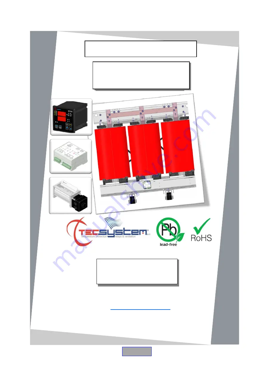
INSTRUCTION MANUAL
TRBH
SYSTEM
TECSYSTEM S.r.l.
20094 Corsico (MI)
Tel.: +39-024581861
Fax: +39-0248600783
ENGLISH
Страница 1: ...O9001 certified quality system http www tecsystem it R 1 1 29 07 20 Translations of the original instructions INSTRUCTION MANUAL TRBH SYSTEM TECSYSTEM S r l 20094 Corsico MI Tel 39 024581861 Fax 39 02...
Страница 2: ...NTROL BOX B1 CONTROL BOX B2 ELECTRICAL CONNECTIONS FANS CONTROL BOX ELECTRICAL CONNECTIONS 15 CONNECTION NOTES 20 11 FANS TEST 12 FAN DIAGNOSTICS 21 13 TG180BH TG360BH TG500BH FANS DIMENSIONS 14 1200B...
Страница 3: ...or smoke contact the assistance LIQUIDS Do not expose the equipment to splashes or drops do not position it in places with humidity exceeding 90 and never touch with wet hands If any liquid penetrates...
Страница 4: ...vice if there is a smell of burning or smoke Contact the Tecsystem technical assistance LIQUIDS Do not expose the product to dripping or splashing liquids Do not place in places with humidity over 90...
Страница 5: ...outputs for motors B1 M1 M2 M3 and B2 M4 M5 M6 230Vac 50 60Hz Range 187 265Vac 50 60Hz 1 digital output for control box B1 B2 BLDC OUT 12VDC DIMENSIONS 106x108 depth 53 50mm Din rail TESTS AND PERFOR...
Страница 6: ...att INPUTS Digital input for the control box connection TESTS AND PERFORMANCE Ambient operating temperature from as indicated in the standard IEC 60076 11 IP40 degree of protection Min and max speed r...
Страница 7: ...on the individual channel see table example speed CH1 table example speed CH1 Temperature CH1 Motor S and Rpm Speed Fan flow rate m h TG180BH TG360BH TG500BH 60 C S0 OFF OFF OFF OFF 61 C S1 1500 220...
Страница 8: ...8 TRBH SYSTEM SYSTEM COMPONENTS Temperature control unit versions NT935BH D NT935BH ETH Control box CB3 BH B1 management bar 1 M1 M2 M3 B2 management bar 2 M4 M5 M6 Fans TG180BH TG360BH TG500BH BH bar...
Страница 9: ...3 poles pitch 5 supply Code 2PL0367 Screws tightening torque 0 5Nm 2 Terminals 3 poles pitch 3 81 control box IN OUT Code 2PL0366 Screws tightening torque 0 25Nm 1 Terminal 12 poles pitch 3 81 motor...
Страница 10: ...olley and centre the positioning of the bar using the central column of the transformer as a reference Fix the bar on the transformer trolley using the appropriate fixing slots suggested M8 bolts plus...
Страница 11: ...lock the fans in the desired position Use the fan flappers to correctly direct the air inside the transformer columns ATTENTION always maintain a safe distance from the windings indicated by the tran...
Страница 12: ...movement avoid deforming the impeller fins Never change the position of the motor If the fan bar is mounted on a transformer the fan s working position must respect the safety distance indicated in t...
Страница 13: ...L BOX BAR B1 and CONTROL BOX BAR B2 using the supplied labels The identification of the two bars will be used to define the connections of the two boxes and of the fans M1 M2 M3 M4 M5 M6 associated wi...
Страница 14: ...ow Power supply for 230Vac 50 60Hz motors it is used to power the B1 M1 M2 M3 box fans or the B2 M4 M5 M6 box fans The earthing cable must always be connected to the earthing terminal ELECTRICAL CONTR...
Страница 15: ...colour 1MN0181 REV 0 A B Connector A motor power supply pin 1 neutral blue pin 2 phase brown pin 3 nc Connector B digital signals for motor signals pin 1 white pin 2 brown pin 3 blue pin 4 black The c...
Страница 16: ...gle fan with the relative digital cable motor signals to the MOTORS CONTROL LINE output of the control box B1 bar digital connection B2 bar digital connection M1 M2 M3 1 White 2 Brown 3 Blue 4 Black 5...
Страница 17: ...0Hz fan lines to the MOTORS POWER SUPPLY input of both control boxes B1 B2 3 In the B2 M1 configuration 2 bars B1 B2 2 connected fans M1 M6 the positioning and connection of the fans must absolutely r...
Страница 18: ...the fans result in anomalies in operation of the TRBH system Connect the motor connector A of the single fan with the relative motor power cable to the MOTORS POWER LINE output of the control box B1...
Страница 19: ...ions of the individual fans connect the 230Vac 50 60Hz fan lines to the MOTORS POWER SUPPLY input of both control boxes B1 B2 M1 M2 Brown Blue Brown Blue Connect the B motor connector of the single fa...
Страница 20: ...ton of the single control box it is possible to start the fan test During the fan test the control box will activate in sequence for approximately 10 seconds on a fan the M1 M2 M3 fans connected to th...
Страница 21: ...or the single motor Fan speed M1 M6 M2 M5 M3 M4 motor over temperature motor temperature over 70 C general motor failure motor blocked or under stress impeller disconnected from the motor shaft motor...
Страница 22: ...22 TRBH SYSTEM TG360BH TG500BH BH BAR DIMENSIONS 1200BH 1MN0167 REV 0 1MN0168 REV 0 1MN0171 REV 0...
Страница 23: ...nly when the product is damaged by causes attributable to TECSYSTEM srl such as manufacturing or components defects The warranty is invalid if the Product proves to have been tampered with modified or...
Страница 24: ...the bars B1 and B2 Clean the fans using only compressed air Contact the TECSYSTEM Technical Department if the problem persists The European Directive 2012 19 EU WEEE has been approved to reduce electr...