


61
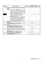
5-2 Troubleshooting of Alarm and Warning
Alarm
Code
Alarm Name
and Description
Corrective Actions
Reset
Method
00 Normal
—
—
Under-voltage
01
The main circuit voltage is below
its minimum specified value.
(190Vac)
Use multi-meter to check whether the input
voltage is within the specified limit. If it can not be
solved, there may be failure inside the Drive.
Turn
ALRS(DI) ON
Over-voltage
(Regeneration error)
02
1. The main circuit voltage is
exceeded maximum allowable
value. (410V)
2. Regeneration voltage is too high.
1. Use multi-meter to check whether the input
voltage is within the specified limit.
2. Check the Parameter
Cn012
if it is setting
correctly.
3. If this alarm appears during operation.
Extend ac/deceleration time or reduce load
ratio in the permitted range. Otherwise, an
external regeneration resistor is needed.
(Please contact your supplier for assistance.)
Turn
ALRS(DI) ON
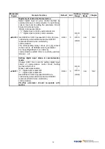
Motor Over-load
03
The drive has exceeded its rated load
during continuous operation. When
the loading is equal to 2 times of
rated loading, alarm occurs within
10sec.
1. Check connection for Motor terminal s (U,V,W)
and Encoder.
2. Adjust the Drive gain, If gain is not correctly
adjusted, it would cause motor vibration and
large current will lead to motor over load.
3. Extend acc/deceleration time or reduce load
ratio in the permitted range.
Turn
ALRS(DI) ON
Drive Over-current
Transistor error
04
Drive main circuit Over current or
Transistor error.
1. Check connection of the motor cable (U,V,W)
and encoder.
Check power cable connection. Refer to the
diagram in Chapter 2.
2. Turn off the power, and turn on again after 30
min. If the alarm still exists, there may be
power module malfunction or noise consider
the drive for test and repair.
Reset Power
Supply
Encoder ABZ phase signal error
05
Motor’s encoder
failure or encoder
connection problem.
1. Check the motor’s encoder connections.
2. Check the encoder if short circuit, poor solder
joints or break.
3. Check the encoder signal terminals CN2-4and
CN2-5 ( power cable 5v)
Reset Power
Supply
Communication error
06
Communication protocol setting error or
Communication time-out is detected.
1. Check parameter setting of communication
function.
2. Check wire connection between drive and
controller.
3. Set a correct value for parameter Cn039
communication time-out or set “0 ” to disable
communication time-out function.
Reset Power
Supply
Multi-function contact setting error
07
Input/output contacts function setting
error.
1. Check parameters Hn501~Hn506 trigger level
selected by 2
nd
digit of Hn 501 to 506should be
the same for all inputs
DI-1
~
DI-6
2.Check parameters setting of
Hn507~Hn509
hould NOT be the same for outputs contact
DO-1~DO-3
Reset Power
Supply
Memory Error
08
Parameter write-in error
Disconnect all command cable then re-cycle the
power. If alarm still occurs, it means the Drive
was failure.
Reset Power
Supply
Содержание JSDE Series
Страница 25: ...25 2 3 2 Position Control Mode Pe Mode Open Collector Digital input and output terminal are programmable ...
Страница 26: ...26 2 3 3 Position Control Mode Pi Mode Digital input and output terminal are programmable ...
Страница 27: ...27 2 3 4 Speed Control Mode S Mode Digital input and output terminal are programmable ...
Страница 28: ...28 2 3 5 Torque Control Mode T Mode Digital input and output terminal are programmable ...


