


48
Parameter Name
&
Function Default
Unit
Setting
Range
Control
Mode
Chapter
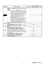
Electronic Gear Ratio Numerator 4
Pn305
Use input contacts GN1 & GN2 to select one of four
electronic Gear Ratio Numerators.
To select Numerator 4, the statue of the input-contacts
GN1 & GN2 should be as follows:
Input Contact GN2
Input Contact GN1
1 1
Note: Input contacts status “1” (ON) and “0” (OFF).
Refer to 5-6-1 to set high or low input logic levels.
1 X
1
│
50000
Pi
Pe
5-4-3
Electronic Gear Ratio Denominator
★
Pn306
Set the calculated Electronic Gear Ratio Denominator
in Pn 306. ( Refer to section 5-4-3).
Electronic Gear Ratio should comply with the formula
below.
0
20
0
20
1
≤
≤
GearRatio
Electronic
1 X
1
│
50000
Pi
Pe
5-4-3
Position complete value
Pn307
Set a value for In position output signal.
When the Position pulse error value is less then
Pn307
output-contact
INP (In position output signal)
will be
activated.
10 pulse
0
│
50000
Pi
Pe
5-4-9
“Incorrect position” Error band Upper limit.
Pn308
When the Position error value is higher then number of
pulses set in
Pn308
, an Alarm message
AL-11
(Position error value alarm) will be displayed.
50000 pulse
0
│
50000
Pi
Pe
5-4-9
“Incorrect position” Error band lower limit.
Pn309
When the Position error value is lower then number of
pulses set in
Pn309
, an Alarm message
AL-11
(Position error value alarm) will be displayed.
50000 pulse
0
│
50000
Pi
Pe
5-4-9
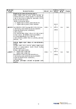
Position Loop Gain 1
Pn310
Without causing vibration or noise on the mechanical
system the position loop gain value can be increased
to increase system response and shorten the
positioning time.
Generally, the position loop bandwidth should not be
higher then speed loop bandwidth. The relationship is
according to the formula below:
5
2
ain
SpeedLoopG
opGain
PositionLo
×
≤
π
40 1/s
1
│
450
Pi
Pe
5-4-6
5-5
Position Loop Gain 2
Pn311
Refer to
Pn310
40 1/s
1
│
450
Pi
Pe
5-4-6
5-5
Position Loop Feed Forward Gain
Pn312
It can be used to reduce the track error of position
control and speed up the response.
If the feed forward gain is too large, it might cause
speed overshoot and
INP
contact repeatedly switch
ON/OFF.
INP
(“In Position” output signal).
0 %
0
│
100
Pi
Pe
5-4-6
5-5
Содержание JSDE Series
Страница 25: ...25 2 3 2 Position Control Mode Pe Mode Open Collector Digital input and output terminal are programmable ...
Страница 26: ...26 2 3 3 Position Control Mode Pi Mode Digital input and output terminal are programmable ...
Страница 27: ...27 2 3 4 Speed Control Mode S Mode Digital input and output terminal are programmable ...
Страница 28: ...28 2 3 5 Torque Control Mode T Mode Digital input and output terminal are programmable ...


