5
Manuale DE.CS 25
Pagina 6 di 19
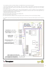
SCHEMA ELETTRICO
I collegamenti richiesti dal deumidificatore si possono suddividere in due tipi: di
potenza, di segnale.
La potenza non è altro che l’alimentazione (230V
-50Hz-1Ph), linea sulla quale è
bene prevedere a monte sia un sezionatore sia un protettore in quanto il fusibile
presente sulla scheda protegge solo la parte circuitale in bassa tensione e non le
utenze(compressore, ventilatore, ecc.).
Il segnale da passare alla macchina è un contatto pulito per la deumidificazione ed
uno per la ventilazione. La scheda gestisce autonomamente la logica di
funzionamento monitorando costantemente il circuito frigorifero ed è in grado di
rilevare situazioni anomale o di cattivo funzionamento bloccando, se del caso, il
compressore.
Tre Led indicano lo stato della macchina:
- Led rosso a centro scheda: presenza alimentazione;
- Led rosso in basso: allarme attivo;
- Led verde in alto: compressore attivo se luce fissa oppure temporizzazione
attiva pre-accensione se lampeggiante.
E’ possibile aumentare la velocità del ventilatore spostando il filo arancione verso il
basso in corrispondenza del morsetto V2 per la velocità media oppure V3 per la
massima velocità.
The connections required by the dehumidifier can be divided into two types: power and signal.
The power is simply the power supply (230V-50Hz-1Ph), a line on which it is good practice to provide both a disconnector
and a protector upstream, as the fuse on the board only protects the low voltage part of the circuit and not the utilities
(compressor, fan, etc.).
The signal to be sent to the machine is a clean contact for dehumidification and one for ventilation. The board independently
manages the operating logic by constantly monitoring the refrigeration circuit and it is able to detect abnormal situations or
malfunctions, blocking the compressor if necessary.
Three LEDs indicate the machine status:
•
Red LED at the centre of the board: power supply present;
•
Red LED at the bottom: alarm active;
•
Green LED at the top: compressor active if the light is steady or pre-start-up timer active if the light is flashing.
It is possible to increase the fan speed by moving the orange wire down to terminal V2 for medium speed or V3 for maximum
speed.
VELOCITÀ ALTA
/ HIGH SPEED
VELOCITÀ MEDIA
/ MEDIUM SPEED
VELOCITÀ BASSA
/ LOW SPEED
ALIMENTAZIONE
/ POWER SUPPLY
230V - 50 Hz
CONSENSO VENTILAZIONE
/ FAN APPROVAL
CONSENSO DEUMIDIFICAZIONE
/ DEHUMIDIFICATION APPROVAL
SONDA TEMPERATURA EVAPORATORE
/ SONDA TEMPERATURA EVAPORATORE
SONDA TEMPERATURA CONDENSATORE
/ SONDA TEMPERATURA CONDENSATORE
VENTILATORE
/ FAN
COMPRESSORE
/ COMPRESSOR
Содержание 30200010
Страница 11: ...11 NOTE NOTES...

