EVO
SELF
| User and Maintenance Manual | EN
37
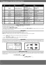
After the password ‘PA2’ has been putted in, press the
and
keys to scroll through to the required function (e.g. UL). Press the
key to
execute the upload. If the operation is successful, the display will show ‘
y
’, if not it will show ‘
n
’.
Upload (UL)
This function uploads the programming parameters from the device.
UPLOAD: device
Copy Card
Format (Fr)
This command is used to format the copy card, an operation which is necessary when using the card for the
fi
rst time.
Important
:
when the copy card has been programmed, the parameter ‘
Fr
’ will delete all data that have been entered. This operation cannot be cancelled.
Download from reset:
Connect the copy card when the device is switched off. When
the device is switched on, the download from the copy card will
begin automatically. At the end of the lamp test, the display will
show ‘
dLy
’ if the operation was successful and ‘
dLn
’ if not.
DOWNLOAD: Copy Card
device
NOTES:
- after the parameters have been downloaded, the device uses the downloaded parameter map settings.
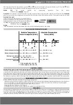
MAX AND MIN TEMPERATURE ALARM
Setpoint - LAL
AFd
Off
Se HAL
AFd
Setpoint - LAL + AFd
Setpoint + HAL - AFd
Setpoint
LAL
AFd
HAL
AFd
LAL + AFd
HAL - AFd
Relative Temperature
Value to setpoint (Att=1)
Absolute Temperature
Value (Att=0)
Temp.
≤
Set + LAL
(only with
LAL<0
*)
Temp.
≥
Set + HAL
(only with
HAL>0*
*)
Temp.
≥
Set + LAL + AFd
o
≥
Set -
I
LAL
I
+ AFd
(LAL < 0*)
Temp.
≤
Set + HAL - AFd
(HAL > 0**)
Temp.
≤
LAL
(
LAL
with sign)
Temp.
≥
HAL
(
HAL
with sign)
Temp.
≥
LAL + AFd
Temp.
≤
HAL - AFd
Minimum temperature alarm
Maximum temperature alarm
Returning from minimum
temp. alarm
Returning from maximum
temp. alarm
* if LAL is negative, Set + LAL < Set
** if HAL is negative, Set + HAL > Set
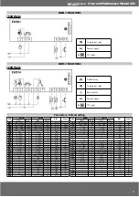
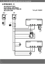
ELECTRICAL WIRING
Attention! Never work on electrical connections when the machine is switched on.
The device is equipped with screw or removable terminals for connecting electric cables with a diameter of 2.5mm
2
(one wire per terminal for power
connections). For the capacity of the terminals, see the label on the instrument. Do not exceed the maximum current allowed; in case of higher loads,
use an appropriate contactor. Make sure the power supply voltage complies with the one required by the instrument. Probes have no connection
polarity and can be extended using a regular bipolar cable (note that the extension of the probes affects the EMC electromagnetic compatibility of
the instrument: pay extreme attention to wiring). Probe cables, power supply cables and the TTL serial cables should be distant from power cables.
RESPONSIBILITY AND RESIDUAL RISKS
ELIWELL CONTROLS SRL shall not be liable for any damages deriving from:
- installation/use other than that prescribed and, in particular, that which does not comply with safety standards anticipated by regulations and/or those given herein;
- use on boards which do not guarantee adequate protection against electric shock, water or dust under the conditions of assembly applied;
- use on boards which allow access to dangerous parts without the use of tools;
- tampering with and/or alteration of the products;
- installation/use on boards that do not comply with the standards and regulations in force.
DISCLAIMER
This manual and its contents remain the sole property of ELIWELL CONTROLS SRL, and shall not be reproduced or distributed without authorization
by ELIWELL CONTROLS SRL. Although great care has been exercised in the preparation of this document, ELIWELL CONTROLS SRL, its employees or
its vendors, cannot accept any liability whatsoever connected with its use. The same applies to any person or company involved in preparing and
editing this document. ELIWELL CONTROLS SRL reserves the right to make any changes or improvements without prior notice.


