background image


-


OPERATORS MANUAL 


Page 17 

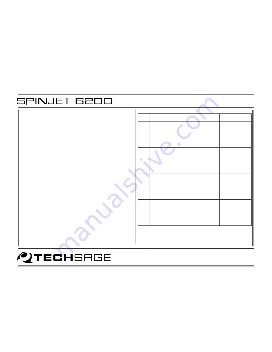
Should the failure or damage come from the SPINJET 6200, use 
the table below to identify possible causes and their remedies. If 
the outcome is ‘Call service’ or unidentified, the contact is 

TechSage or its reseller. 
 
In this case, reset the error message, if any, on the panel by 

keeping the power button pressed for more than two seconds. 
Turn the SPINJET 

off

. Make sure that DUPLEXER has been set to 

NO on the Printer. Send jobs using single side, but otherwise 
similar to the trouble condition, to the printer and check whether 
it passes through the SPINJET and exits from its upper slot. If 

this can be done without the occurrence of a problem, the 
SPINJET should be left in this position for continued 

single

 sided 

printer use until service can be carried out. 


In all other cases, leave the SPINJET Front Unit tilted down and 
turned off. 


Please note:

 Setting DUPLEXER to NO will disable all 

communication between the Printer and the SPINJET and double 

sided printing is disabled. 


No. 

Problem 

Most probable 

cause 

How to solve 

problem 

1a 

Flashing yellow INFO 
LED switching on and 
Error 01 indi-cated on 

Designjet control 
panel. 

New print job 
has been sent 
when SPINJET 

in lower 
position. 

Move SPINJET to 
upper position 
and press Enter 

on printer 
display. 

1b 

Flashing yellow INFO 
LED switching on and 
Error 01 indi-cated on 

Designjet control 
panel. 

Front unit not 
butted fully up 
against the 

Designjet. 

Check for proper 
contact with 
Designjet at 

rubber bumper. 

Flashing yellow INFO 

LED switching on and 
Error 02 indi-cated on 

Designjet control 
panel. 

SPINJET moved 

to lower 
position during 

print job. 

Check printer 

and move 
SPINJET to upper 

position when 
Printer enters 
‘Ready’ mode. 

Flashing yellow INFO 
LED switching on and 
Error 03-06 indicated 

on Designjet control 
panel. 

Inoperative 
sensor or 
motor. 

Call service. 


Содержание Spinjet 6200

Страница 1: ...sable the safety switch in the right side of the SPINJET 6200 Only specially trained personnel should carry out tasks for test or service purposes requiring operation with any of the covers removed The instructions for inspection and replacement of wear and spare parts must be followed Connect SPINJET 6200 to earthed mains outlet only rated 100 120VAC or 200 240VAC 50 60Hz one phase Apply a power ...

Страница 2: ...ations 19 7 1 Technical Specifications 20 7 2 Safety Specifications 20 7 3 EMC Specifications 21 7 4 EU Declaration of Conformity 22 1 General description Figure 1 SPINJET 6200 is intended for use on the Designjet Z6200 and Z6100 HP large format printer models referred to as the Printer only The instructions for installation and operation of both Printer and SPINJET 6200 must be followed SPINJET 6...

Страница 3: ...are Receive a sheet which is printed from the Roll by the Printer Feed the sheet back into the Printer for reverse side printing Manage the Media from the Roll while carrying out reverse side printing The following cartoon explains how this handling is taking place Figure 2 Figure 3 Step 2 The Gate flips up when receiving a double sided job Step 1 Printer is ready to print on roll media ...

Страница 4: ... OPERATORS MANUAL Page 4 Figure 4 Figure 5 Step 3 Printer feeds media into the SPINJET while printing front page Step 4 Front page is finished ...

Страница 5: ... OPERATORS MANUAL Page 5 Figure 6 Figure 7 Step 5 SPINJET grabs media Step 6 The Printer cuts media into a sheet ...

Страница 6: ... OPERATORS MANUAL Page 6 Figure 8 Figure 9 Step 7 Front edge of sheet is retracted into the SPINJET Step 8 Sheet 1 is held until the printer is ready to receive sheet for reverse side printing ...

Страница 7: ... OPERATORS MANUAL Page 7 Figure 10 Figure 11 Step 9 SPINJET grabs roll media and unloads it from printer Step 10 Printer is ready to receive sheet from SPINJET ...

Страница 8: ... OPERATORS MANUAL Page 8 Figure 12 Figure 13 Step 11 SPINJET loads sheet to printer Step 12 SPINJET releases the grip of sheet ...

Страница 9: ... OPERATORS MANUAL Page 9 Figure 14 Figure 15 Step 13 Back side of double sided job is printed Step 14 Back side is finished ...

Страница 10: ... OPERATORS MANUAL Page 10 Figure 16 Figure 17 Step 15 SPINJET loads roll to printer Step 16 SPINJET lets go of roll media and has finished double sided job ...

Страница 11: ... position Please refer to Section 6 Troubleshooting Tilting up the Front Unit must only be done when the Printer is when Ready is indicated on the Printer Control Panel An Error 02 will occur if moving the Front unit to lower position during a print job Please refer to Section 6 Troubleshooting Leave the Front Unit in upper position when the Printer carries out a calibration The Front Unit must be...

Страница 12: ...the Core Adaptors 3 supplied with the Printer as illustrated on Figure 19 Adaptors must be installed in both ends Figure 19 Check that the Media Roll has been pressed fully up against the Roll stopper and no gap between the Media roll and roll stopper is present as illustrated on Figure 20 Figure 20 Install Core Adaptors Media Roll Roll stopper No Gap ...

Страница 13: ...efer to the section Load and unload Media in the Pocket Guide for further instructions on how to load Media When the Printer has completed the normal roll loading procedure the Front Unit must be gently raised to the upright position DO NOT release the grip of the Front Unit before it rests against the Printer as this may damage the SPINJET 3 2 Trim Waste Strips Occasionally the Printer produces t...

Страница 14: ...g should be observed Set up the Printer as follows PRINTER SETUP ACCESSORIES DUPLEXER YES The SPINJET will perform following automatic SPINJET sequence when setting DUPLEXER from NO to YES Initialize followed by Ready Please note Unload Roll media from Printer before setting DUPLEXER to YES Setting DUPLEXER to NO will disable all communication between the Printer and the SPINJET and double sided p...

Страница 15: ... to Section printer Set Up 3 Standby red Standby LED constantly on Standby mode indicates that the SPINJET is fully functional but it is unknown whether communication with the Printer is possible SPINJET has most likely been restarted or reset after the printer has been turned on if the printer is set up according to Section Printer Set Up and SPINJET is Standby When a print job is sent to the Pri...

Страница 16: ...iles must be sent to the SPINJET from an application RIP or interface that supports the SPINJET Possible methods available at present are listed below TechSage has a two legged interface strategy User interface via the SPINFLOW interface Direct integration by the vendors of Prepress Workflow Systems RIPs 5 1 SPINFLOW SPINFLOW is the enhanced data interface between host Pre Press Systems and the HP...

Страница 17: ...NJET Front Unit tilted down and turned off Please note Setting DUPLEXER to NO will disable all communication between the Printer and the SPINJET and double sided printing is disabled No Problem Most probable cause How to solve problem 1a Flashing yellow INFO LED switching on and Error 01 indi cated on Designjet control panel New print job has been sent when SPINJET in lower position Move SPINJET t...

Страница 18: ...o YES b Check harness between SPINJET and Designjet 7 The SPINJET will not enter Ready state when Initializing Printer SPINJET is in upper position Connection between SPINJET and Designjet has been lost c Call service No Problem Most probable cause How to solve problem a Use media according to specified quality parameters 8 Print head collides with media when Designjet is preparing to print page 2...

Страница 19: ... Raise Front unit 10 Printer gives error message Roll misaligned on printer display Roll position tolerances of the printer exceeded because of unsuccessful roll capture or feed b Check that Media Roll is installed correct see 3 1 Loading Media 11 Printer does not respond to new jobs Printer error Turn off Designjet and restart ...

Страница 20: ... to handle the media or to the accuracy of the print Media sizes Width 610 1067 mm Length 594 2500 mm imposition proofing Length 594 4000 mm banner and poster production Roll core diameter 3 Margins Top bottom margin 55 mm minimum Curl 30 mm max Electrical power source 100 120VAC 200 240VAC 50 60Hz one phase and earth 1 4 0 7A Electrical power consumption Less than 12 watts when operating Dimensio...

Страница 21: ...ficate test reference no 132333 01 7 3 EMC Specifications European Union Complies with EMC Directive 89 336 EEC EN 55022 1998 A2 2003 Information technology equipment Radio disturbance characteristics Limits and methods of measurement Class B EN 55024 1998 A1 2001 A2 2003 Information technology equipment Immunity characteristics Limits and methods of measurement EN 61000 3 2 2000 Limits for harmon...

Страница 22: ...e Low Voltage Directive 73 23 EEC as amended The EMC Directive 89 336 EEC as amended The apparatus is manufactured in accordance with the following parts clauses of harmonized European standards The Machinery Directive EN 292 1 1993 4 2 4 3 EN 292 2 1993 3 9 6 2 2 Annex A 1 5 1 1 6 3 4 2 1 4 2 1 4 4 3 3 4 4 2a as amended EN 1050 1997 Annex A The Low Voltage Directive EN 60950 2000 The EMC Directiv...

Отзывы: