


380
1) In the WAN mode, system opens the main stream of the first channel to monitor by
default. The open/close button on the left pane is null.
2) You can select different channels and different monitor modes at the bottom of the
interface.
Important
The window display mode and the channel number are by default. For example, for
the 16-channel, the max window split mode is 16.
3) Multiple-channel monitor, system adopts extra stream to monitor by default. Double
click one channel, system switches to single channel and system uses main stream to
monitor. You can view there are two icons at the left top corner of the channel number for
you reference. M stands for main stream. S stands for sub stream (extra stream).
4) If you login via the WAN mode, system does not support alarm activation to open the
video function in the Alarm setup interface.
Important
For multiple-channel monitor mode, system adopts extra stream to monitor by default.
You can not modify manually. All channels are trying to synchronize. Please note the
synchronization effect still depends on your network environments.
For bandwidth consideration, system can not support monitor and playback at the
same time. System auto closes monitor or playback interface when you are searching
setup in the configuration interface. It is to enhance search speed.
5.8
Setup
5.8.1 Camera
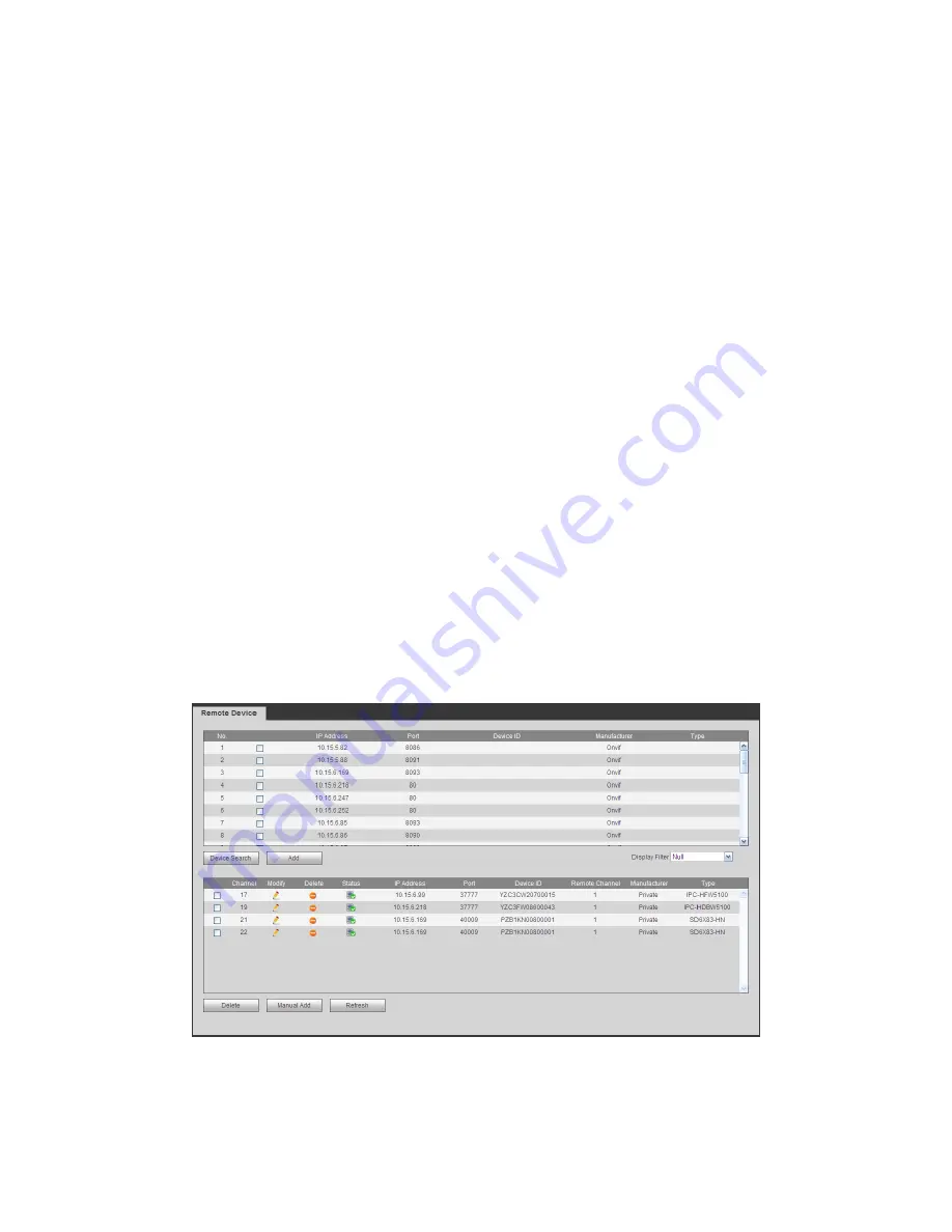
5.8.1.1 Remote Device (For digital channel only)
Remote device interface is shown as below. See Figure 5-17.
Figure 5-17
Содержание TRIDVR-EL16M4
Страница 1: ...Elite Series Tribrid User s Manual TRIDVR EL16M4...
Страница 8: ...x APPENDIX F COMPATIBLE WIRELESS MOUSE LIST APPENDIX G EARTHING...
Страница 17: ...204 2 3 5 1U Series Please refer to the following figure for detailed information 2 3 Connection Sample...
Страница 85: ...278 Figure 4 72 Figure 4 73...
Страница 116: ...309 Figure 4 105 Figure 4 106...
Страница 117: ...310 Figure 4 107 Figure 4 108...
Страница 133: ...326 Figure 4 125 Figure 4 126...
Страница 134: ...327 Figure 4 127 Figure 4 128...
Страница 135: ...328 Figure 4 129 Figure 4 130...
Страница 138: ...331 Figure 4 134 Figure 4 135...
Страница 145: ...338 Figure 4 145 Figure 4 146 4 11 4 1 2 2Trigger Snapshot...
Страница 147: ...340 Figure 4 148 Figure 4 149 4 11 4 1 2 3Priority...
Страница 164: ...357 Figure 4 170 For digital channel the interface is shown as below See Figure 4 171 Figure 4 171...
Страница 178: ...371 Figure 4 188...
Страница 196: ...389 Figure 5 26 5 8 2 Network 5 8 2 1 TCP IP The single Ethernet port interface is shown as in Figure 5 27...
Страница 213: ...406 Figure 5 55 Figure 5 56...
Страница 226: ...419 Figure 5 71 Figure 5 72...
Страница 233: ...426 Figure 5 81 Figure 5 82 Figure 5 83 Please refer to the following sheet for detailed information...
Страница 276: ...469 448K 196M 512K 225M 640K 281M 768K 337M 896K 393M 1024K 450M 1280K 562M 1536K 675M 1792K 787M 2048K 900M...


