Techpro NVR-PRE16C-P Скачать руководство пользователя страница 9

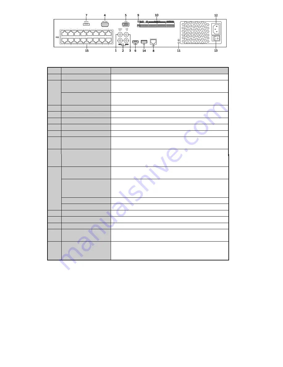
No. 

Item 

Description 

VIDEO OUT 

BNC connector for video output. 

CVBS AUDIO OUT 

BNC connector for audio output. This connector is synchronized with 

CVBS video output. 

VGA AUDIO OUT 

BNC connector for audio output. This connector is synchronized with 

VGA video output. 

LINE IN 

BNC connector for audio input. 

RS-232 Interface 

Connector for RS-232 devices. 

VGA 

DB9 connector for VGA output. Display local video output and menu. 

HDMI 

HDMI video output connector. 

eSATA (Optional) 

Connects external SATA HDD, CD/DVD-RM. 

LAN Interface 

1 network interface provided for NR500/NR50P and 2 network 

interfaces for NRA00/NRA0R. 

Termination Switch 

RS-485 termination switch. 
Up position is not terminated. 

Down position is terminated with 120Ω resistance. 

10 

RS-485 Interface 

Connector for RS-485 devices. T+ and T- pins connect to R+ and R- 

pins of PTZ receiver respectively. 

Controller Port 

D+, D- pin connects to Ta, Tb pin of controller. For cascading devices, 

the first NVR’s D+, D- pin should be connected with the D+, D- pin of 

the next NVR. 

ALARM IN 

Connector for alarm input. 

ALARM OUT 

Connector for alarm output. 

11 

GROUND 

Ground(needs to be connected when NVR starts up). 

12 

AC 100V ~ 240V 

AC 100V ~ 240V power supply. 

13 

POWER 

Switch for turning on/off the device. 

14 

USB interface 

Universal Serial Bus (USB) ports for additional devices such as USB 

mouse and USB Hard Disk Drive (HDD). 

15 

Network  Interfaces  with 

PoE  function  (supported 

by NR50P) 

Network interfaces for the cameras and to provide power over Ethernet. 

Содержание NVR-PRE16C-P

Страница 1: ...2yr Warranty 1080p Resolution Prime Series NVR User s Manual Motion Activated Recording PTZ Control View From Anywhere NVR PRE16C P...

Страница 2: ...sing of Alarm Connectors Controller Connection Specifications HDD Storage Calculation Chart Accessing by Web Browser Logging In Live View Recording Playback Log Menu Operation Menu Structure Startup a...

Страница 3: ...sure there is ample room for audio and video cables 3 When routing cables ensure that the bend radius of the cables are no less than five times than its diameter 4 Connect both the alarm and RS 485 ca...

Страница 4: ...s on the rear and side panel 2 Connect one end of the data cable to the motherboard of NVR and the other end to the HDD 3 Connect the power cable to the HDD 4 Place the HDD on the bottom of the device...

Страница 5: ...1 Remove the cover from the NVR by unfastening the screws on the rear and side panel...

Страница 6: ...by a keyboard or by the IR remote control with the address of 255 Indicator turns green when the DVR is controlled by IR remote control with the address from 1 254 and keyboard at the same time and t...

Страница 7: ...t 3DEF F2 Enter numeral 3 Enter letters DEF In PTZ Control mode the F1 button can be used to zoom in zoom the PTZ camera The F2 button can be used to cycle through tab pages 4GHI ESC Enter numeral 4 E...

Страница 8: ...sed to zoom out zoom the PTZ camera In live view or playback mode the F1 button can be used to switch between main and spot video output 3DEF F2 Enter numeral 3 Enter letters DEF In PTZ Control mode t...

Страница 9: ...85 termination switch Up position is not terminated Down position is terminated with 120 resistance 10 RS 485 Interface Connector for RS 485 devices T and T pins connect to R and R pins of PTZ receive...

Страница 10: ...1A safely To connect an AC load jumpers should be left open you must remove the jumper on the motherboard in the NVR Use an external relay for safety as shown in the figure above There are 4 jumpers J...

Страница 11: ...from the KB terminal block 2 Unfasten stop screws from the KB D D pluggable block insert signal cables into slots and fasten stop screws Ensure signal cables are in tight 3 Connect Ta on controller t...

Страница 12: ...720 60Hz 1024 768 60Hz Audio output 2 ch BNC Linear 600 Decoding Live view Playback resolution 5MP 3MP 1080P UXGA 720P VGA 4CIF DCIF 2CIF CIF QCIF Capability 16 ch 720P 8 ch 1080P Hard disk SATA 8 SA...

Страница 13: ...ding Live view Playback resolution 5MP 3MP 1080P UXGA 720P VGA 4CIF DCIF 2CIF CIF QCIF Capability 8 ch 720P 4 ch 1080P 16 ch 720P 8 ch 1080P 16 ch 720P 8 ch 1080P Hard disk SATA 4 SATA interfaces for...

Страница 14: ...ate Storage Used 96K 42M 128K 56M 160K 70M 192K 84M 224K 98M 256K 112M 320K 140M 384K 168M 448K 196M 512K 225M 640K 281M 768K 337M 896K 393M 1024K 450M 1280K 562M 1536K 675M 1792K 787M 2048K 900M 4096...

Страница 15: ...er name is admin and password is 12345 You may use one of the following listed web browsers Internet Explorer 6 0 Internet Explorer 7 0 Internet Explorer 8 0 Internet Explorer 9 0 Internet Explorer 10...

Страница 16: ...dow by clicking the mouse 2 Double click a camera from the device list to start the live view 3 You can click the button on the toolbar to start the live view of all cameras on the device list Refer t...

Страница 17: ...tart Time and End Time Up to 8 segments can be configured and each segment cannot be overlapped 2 Select a Record Type The record type can be Continuous Motion Alarm Motion Alarm Motion Alarm and VCA...

Страница 18: ...ack status including channel number and playback speed 6 Calendar You can select the date to play Start Playback Steps 1 Click Playback on the menu bar to enter playback interface 2 Click the camera f...

Страница 19: ...ove the mouse to the icon and edit the required parameters for transcoded playback including Resolution Bitrate and Frame Rate 3 Click the button if it turns to then the trancoding process is compelet...

Страница 20: ...of the NRA00 NR500 and NR50P Series NVR The menu structure of the NRA0R Series NVR Startup and Shutdown Proper startup and shutdown procedures are crucial to expanding the life of the NVR To start you...

Страница 21: ...menu Menu Shutdown 2 Select the Shutdown button 3 Click the Yes button Live View Some icons are provided on screen in Live View mode to indicate different camera status These icons include Live View I...

Страница 22: ...you can click the One couch Adding button to add all the online IP cameras The added camera is marked in white while the camera has not been added is marked in yellow Explanation of the icons Icon Exp...

Страница 23: ...the checkbox of Channel No in the pop up window as shown in the following figure and click OK to finish adding One touch RAID Configuration Purpose For the NRA0R series NVR the disk array must be conf...

Страница 24: ...completed click OK button in the pop up message box to finish the settings Recording Before you start Make sure that the HDD has already been installed If not please install a HDD and initialize it Y...

Страница 25: ...ck the Yes button in the popup Attention message box to confirm the settings Then all the channels will start to record in the selected mode Playback Play back the record files of a specific channel i...

Страница 26: ...ls during playback process 2 Playback management The toolbar in the bottom part of Playback interface can be used to control playing process Just check the channel or channels if you want to switch pl...

Страница 27: ...uide of Network Video Recorder 31 2 Enter Export interface choose backup device and click Export button to start exporting 3 Check backup result Choose the record file in Export interface and click bu...

Отзывы: