Technosoft 2018
34
iPOS4808 VX Technical Reference
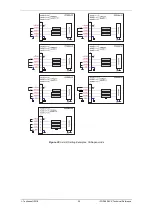
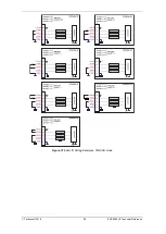
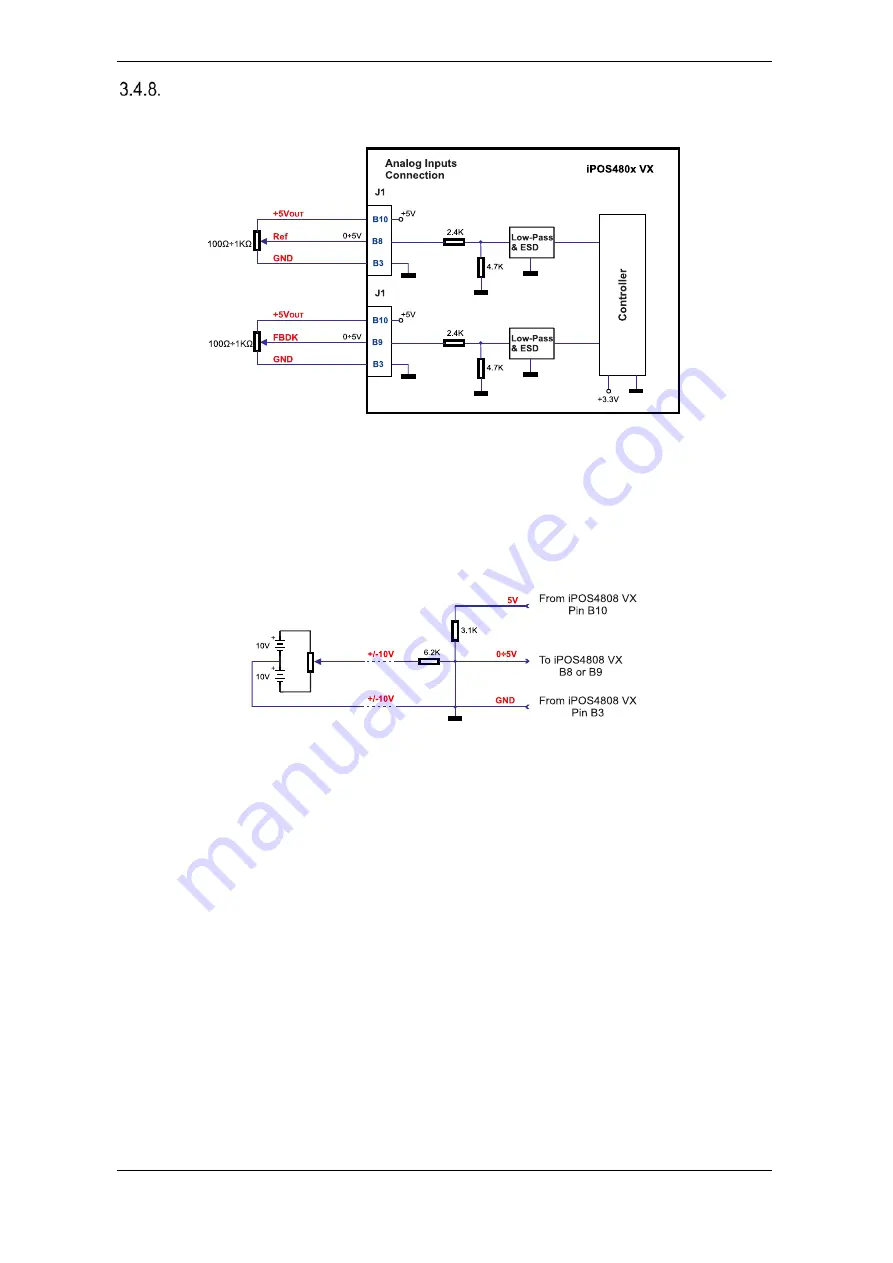
Analog Inputs Connection
3.4.8.1
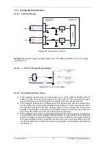
0-5V Input Range
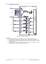
Figure 3.13.
Analog inputs connection
Remark: Default input range for analog inputs is 0÷5 V for REF and FBDK. For a +/-10 V range,
see Figure 3.14.
3.4.8.2
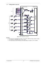
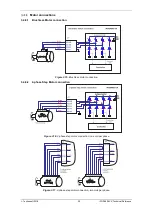
+/- 10V to 0-5V Input Range Adapter
Figure 3.14.
+/-10V to 0-5V adapter
3.4.8.3
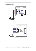
Recommendation for wiring
a) If the analogue signal source is single-ended, use a 2-wire twisted shielded cable as
follows: 1s
t
wire connects the live signal to the drive input; 2
nd
wire connects the source
ground to the drive ground; shield will be connected to the drive ground terminal.
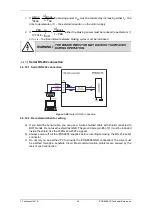
b) If the analogue signal source is differential and the signal source ground is isolated from
the drive GND, use a 2-wire twisted shielded cable as follows: 1s
t
wire connects the source
plus (positive, in-phase) to the drive analogue input; 2
nd
wire connects the source minus
(negative, out-of-phase) to the drive ground (GND). Shield is connected only at the drive
side, to the drive GND, and is left unconnected at the source side.
c) If the analogue signal source is differential and the signal source ground is common with
the drive GND, use a 2-wire shielded cable as follows: 1s
t
wire connects the source plus
(positive, in-phase) to the drive analogue input; 2
nd
wire connects the source ground to the
drive ground (GND); shield is connected only at the drive side, to the drive GND, and is left
unconnected at the source side. The source minus (negative, out-of-phase) output remains
unconnected.


