Page 31 sur 72
www.technomark-marking.com
TECHNOMARK
1 Allée du développement
42350 LA TALAUDIÈRE (France)
Tel : +33 (0) 4 77 22 25 91
Fax : + 33 (0) 4 77 22 38 93
E-mail : [email protected]
User Guide GRAPHIX_v1.4_UK
TRAÇABILITÉ CRÉATIVE
CREATIVE TRACEABILITY
1)
Marking head/Focussing lens
The marking head (scanner), in which the laser source arrives, includes two mirrors mounted on galvanometric motors.
These mirrors divert the ray in direction X and direction Y, according to the graphics to be reproduced. The diverted
laser ray is then concentrated by an F-Theta focussing lens before being aimed at the part to be marked.
Below is a table of currently available F-Theta focussing lenses:
F-Theta scanning lenses
ƒ
= 160S (M39)
ƒ
= 254S (M39)
Option
Lens fixing
mm
39
39
Working distance
mm
183 +/-5
280 +/-4
Fixing distance
mm
197 +/-6*
300 +/-5**
Marking area
mm
2
100 x 100
140 x 140
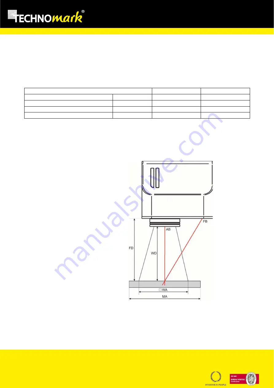
The working distance is defined as the distance between the centre of the marking area (defined in the focal plane)
and the lower edge of the T-theta focussing lens See the figure below:
WD
: Working distance
FD
: Fixing distance
MA
: Part to be marked
WA
: Marking area
AB
: aiming beam
FB
: Focussing beam
For systems equipped with the F-Theta 160S lens, optical focussing is obtained by lining up the aiming beam with the
focussing beam.


