background image


6

(up to 1 Megabit/sec) or non-standard baud 
rates easily.  The PC/104 OSC signal is 
always used as the clock source except when 
a crystal oscillator is installed.  When a crystal 
oscillator is installed, it is always used to 
derive the baud clock. 


4.  COM Port Selection  

The four COM ports can be 
configured as COM1 thru 
COM24.  Jumpers (labeled 
COM1, COM2, COM4 and JP3) 
are used to select the base COM 
port using a binary weighting.  
COMA is always the base COM 
port selected.  For example, if the 
four COM ports are to be 
configured as COM5 thru COM8 
then jumpers “COM1” and 
“COM4” should be installed (1 + 4 
= 5).  In this case COMA would 
be COM5 and COMB, COMC, 
and COMD would be COM ports 
COM6, COM7, and COM8 
respectively.   

Table 3 documents jumper 
settings and the base COM port 
selected. 

PLEASE NOTE: 

Not all serial 

adapter cables are alike!  We are 
aware of at least two 'standard' 
pinouts for these cables. If you did 
not purchase your serial adapter 
cables from us, this may be an issue 
if the serial ports are not working. 


 5 

10 9  8  7  6 

Figure 1 - Serial Port Header Pin Location 

Pin 1 is labeled with a dot in the legend 


Pin  RS-232   RS-422    RS-485 

 1 


   TX+ 

 RX/TX+ 

 2 

 RXD 


 3 

 TXD 


 4 


   RX+ 


 5 

 GND 

  GND 

   GND 

 6 


   TX- 

 RX/TX- 

 7 

 RTS 


 8 

 CTS 


 9 


   RX- 


10  


Table 2 

 Pinout for COM_C and COM_D Headers 


Jumper

COM1

Jumper 

COM2

Jumper 

COM4

Jumper

JP3 

Control  

Reg. Base 

Address 

Base COM 

Port 

Address 

Yes No  No  No  230h 

COM1 

No Yes No  No  230h 

COM2 

Yes Yes  No  No  230h 

COM3 

No No Yes No  230h  COM4 

Yes No Yes No 

234h COM5 

No Yes Yes No  234h 

COM6 

Yes Yes Yes  No  234h 

COM7 

No No No No  238h  COM9 

Yes No  No Yes  240h COM13 

No Yes No Yes  240h  COM14 

Yes Yes  No  Yes  240h 

COM15 

No No Yes Yes 240h  COM16 

Yes No Yes Yes 

244h COM17 

No Yes Yes Yes  244h  COM18 

Yes Yes Yes Yes  244h 

COM19 

No No No Yes 248h  COM21 

                   Table 3 – Base COM port Selection


Содержание TS-SER4

Страница 1: ...i TS SER4 Manual...

Страница 2: ...lls AZ 85268 480 837 5200 FAX 837 5300 info embeddedx86 com http www embeddedx86 com This revision of the manual is dated June 05 2009 All modifications from previous versions are listed in the append...

Страница 3: ...tside of the package This limited warranty does not cover damages resulting from lightning or other power surges misuse abuse abnormal conditions of operation or attempts to alter or modify the functi...

Страница 4: ...PC 104 Bus Interface 5 3 Serial Ports 5 4 COM Port Selection 6 5 Control and Status Registers 7 6 Interrupt Selection 8 7 RS 485 and RS 422 9 8 2X Baud Clock 9 9 Jumpers JP1 JP2 9 10 Temperature Rang...

Страница 5: ...onfigurations if they are necessary 3 Serial Ports The two serial ports that are labeled COM_A and COM_B support RS 232 levels only These two ports support the full complement of standard RS 232 hands...

Страница 6: ...l serial adapter cables are alike We are aware of at least two standard pinouts for these cables If you did not purchase your serial adapter cables from us this may be an issue if the serial ports are...

Страница 7: ...rs are documented in Table 5 below The first three registers are Read Only while in the fourth register bit 7 is Read Write and bits 0 6 are Read Only For all registers if a condition is true a logic...

Страница 8: ...and COM_C interrupts are routed to the lower IRQ and COM_B and COM_D interrupts are routed to the higher IRQ as shown in Table 6 The Interrupt status register can be read to determine which COM port i...

Страница 9: ...r labeled 2x Baud can be installed to cause all baud rates to be twice as high as the standard UART programming would indicate For example when a divisor of 1 written into the UART baud rate register...

Страница 10: ...10 10 Temperature Range The TS SER4 is available in both standard temperature 0 70 degrees Celsius and in extended temperature range of 40 to 85 degrees Celsius...

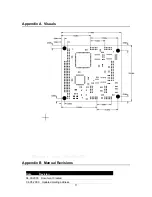
Страница 11: ...11 Appendix A Visuals Appendix B Manual Revisions Date Revision 04 30 2003 Document Created 06 05 2009 Updated mailing address...

Отзывы: