D
GB
F
5
2. Skew Einstellung
(Zeichnung 2)
Die Satelliten ASTRA befinden sich auf
der Position 19,2° Ost. Bekanntlich wird
in zwei Polarisationsebenen gesendet,
nämlich horizontal und vertikal. Durch
die Krümmung der Erdoberfläche und
die Position der Satelliten treffen diese
Mikrowellen in einer leichten Schräglage
auf die Erde. Aus diesem Grund muß
die ASTRAPLUS SATENNE um diese
Schräglage korrigiert werden. Ermitteln
Sie bitte aus Tabelle (1) den geographi-
schen Längen-und Breitengrad Ihres
Installationsstandortes. In der Tabelle (2)
können Sie den Skew-Winkel (Verdre-
hungswinkel) ablesen. Beispiel für Daun:
Längengrad 6 Grad 50 Minuten Ost,
Breitengrad 50 Grad 11 Minuten Nord,
Verdrehungswinkel -1. Anschließend
verdrehen Sie die Antennenhalterung
bis alle 4 Eckpunkte mit der Markierung
(-1) übereinstimmen. Danach können
Sie die Imbusschrauben fest anziehen.
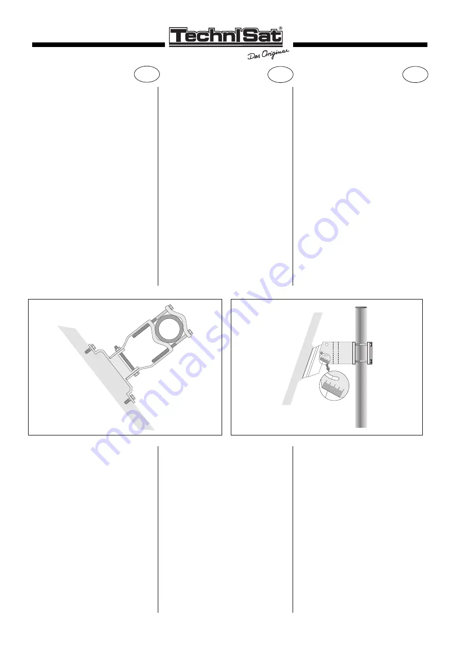
3. Montage der Masthalterung
(Zeichnung 3)
Setzen Sie die Masthalterung wie in Zei-
chung (3) abgebildet zusammen. Die
vier Imbusschrauben stecken Sie von
der rechten Seite* in die dafür vorgese-
henen Bohrungen und ziehen sie hand-
fest an. Benutzen Sie für den Zusam-
menbau die beiliegenden Imbusschrau-
ben, Unterlegscheiben und Sechskant-
muttern.
4 holes in the support are to the top of
the antenna, lightly fastening the 4 scr-
ews with spring washers, so that it is
possible to lightly rotate it.
2. Skew Adjustment
(picture 2)
The ASTRA satellite is situated at 19,2°
east. As is already known, 2 polarisation
levels are used, ie. horizontal and verti-
cal. Due to the curvature of the earth's
surface and the position of the satellite,
the microwaves meet in an oblique posi-
tion to the earth. On this basis the
ASTRAPLUS SATENNE must be adju-
sted. Determine from table (1) the latitu-
de and longitude of your location and in
table (2) look up to skew angle for your
location. Turn the antenna support until
all 4 corner points correspond with the
marking appropriate to the skew angle
(see figure 2). After this you can tighten
the screws.
3. Mounting of the “U” Bracket (4)
(picture 3)
Align the “U” bracket on the support
with slotted holes at the bottom position
(figure 3) and pass the two long bolts
through. Please note that the two holes
on the left side are threaded and the
bolts should be passed right to left when
viewed from the back with the arrow at
the top. The spring washers and nuts
should be put on and then loosely
fastened.
2. Réglage à l’aide du “SKEW”
(figure 2)
Les satellites ASTRA sont co-position-
nés à 19,2°. L’émission s’effectue dans
2 polarisations, soit horizontale, soit ver-
ticale. Du fait de l’inclinaison de la surfa-
ce de la terre, les micro-ondes atteignent
la terre suivant une ligne légèrement dia-
gonale. Pour cette raison, il faut orienter
la SATENNE ASTRAPLUS en fonction
de cet axe. Veuillez vous reporter au
tableau (1) pour trouver les longitudes et
latitudes géographiques de votre lieu
d’installation. Dans le tableau (2) vous
pourrez lire la correction d’angle SKEW.
Exemple pour Lyon:
Longitude 4 degrés 51 minutes Est, lati-
tude 45 degrés 45 Nord
correspond à un angle SKEW +6
Tournez ensuite la fixation de l’antenne
jusqu’à ce que les 4 coins coïcident
avec le préperçage (voir schéma 2).
Vous pourrez ensuite serrer fortement
les vis.
3. Montage de la fixation
Fixer légèrement les 4 vis afin de per-
mettre une légère rotation (voir schéma
3).
➃
30
20
➄
* (mit Blickrichtung auf die Antennenrückseite, Pfeil nach oben)


