http://servis-manual.com/
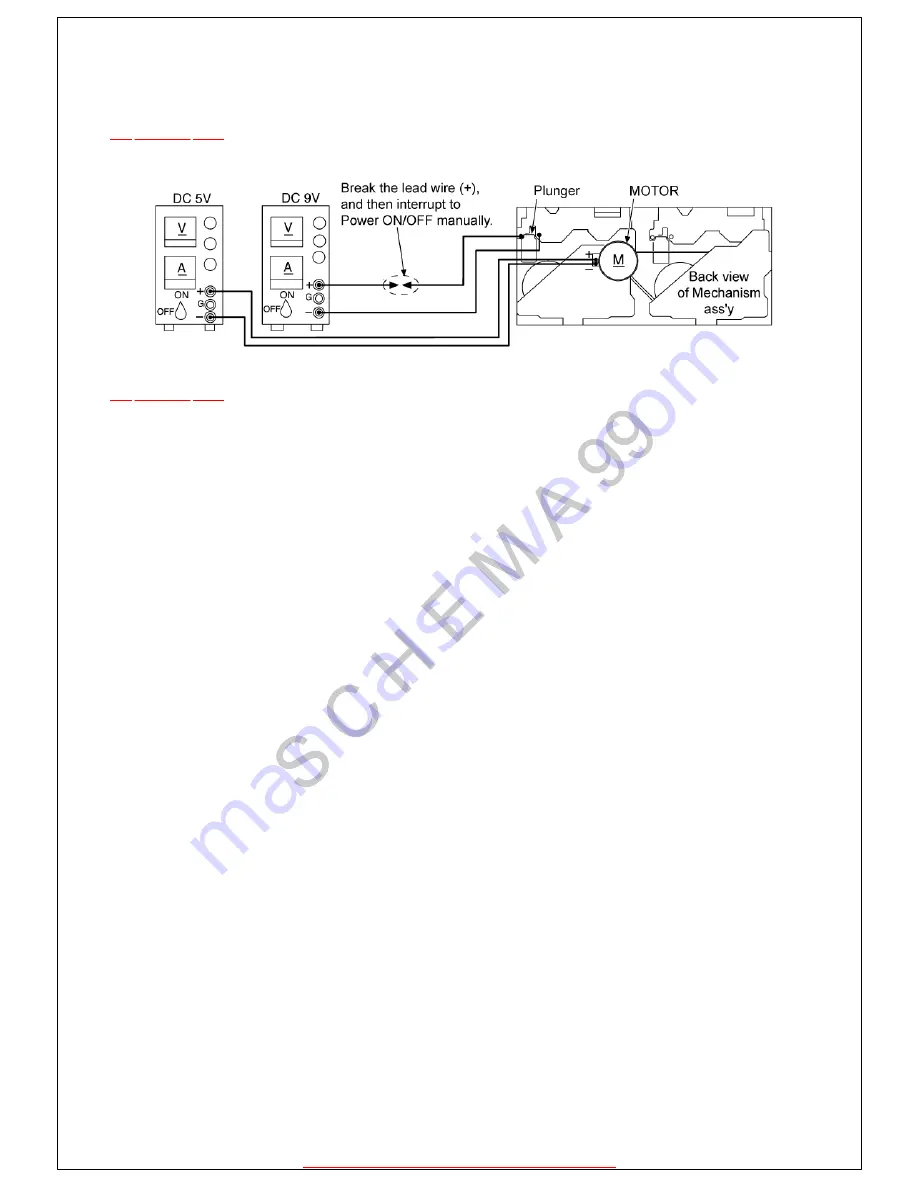
14.1.1 Connection Diagram Between the Mechanism Ass’y and Power Supply/(MOTOR and Plunger)
TOP
PREVIOUS
NEXT
Fig. 14-1.
@
Страница 1: ...l TOP NEXT AD0102028C2 Cassette Deck l RS DV250 AR 2 Mechanism series Colour S Silver Type Area E Europe 2001 Matsushita Electric Industrial Co Ltd All rights reserved Unauthorized copying and distrib...
Страница 2: ...rror code on the FL display of the Tuner Amplifier SA EH770 The system control IC and FLdisplay are part of the Tuner Amplifier so make sure the system has been connected properly before using this fu...
Страница 3: ...d TOP PREVIOUS NEXT l Metal tape Recorded music tape with only one erasure prevention tab intact use middle portion of tape l Normal tape CrO2 tape Recorded music tape with both erasure prevention tab...
Страница 4: ...unit 2 Make sure that no tape is inserted in the cassette deck Service mode cannot be selected with a tape inserted in the cassette deck 3 Press the DOLBY NR button for about 2 seconds and keep pressi...
Страница 5: ...L display Symptom Cause H01 Cassette deck does not operate correctly Faulty cassette deck mechanism mode detect switch Deck 1 S951 Deck 2 S971 plunger and capstan motor Check and replace H02 Unit does...
Страница 6: ...e metal tape intact erasure prevention tab on the left side 7 Close the Deck 2 cassette holder 8 Press the Rewind button Refer to Fig 5 3 Tape rewinds for about 2 seconds then stops 9 Open the Deck 2...
Страница 7: ...rvice mode TOP PREVIOUS NEXT 1 Press the STOP button for more than 5 seconds Diagnostic contents stored in memory for both Deck 1 and 2 are erased 2 Remove the cassette tape from the cassette holder 3...
Страница 8: ...FM Adjust the azimuth screw until the outputs of the L R ch are maximized Refer to Fig 13 2 Make sure that thedifference in the peak level between the left and right channels does not exceed 0 5 dB 4...
Страница 9: ...eck 2 indicatorwill blink Normal speed Standard value 3000 45 Hz 1 Connect the measuring instrument as shown in Fig 13 3 2 Playback the middle portion of test tape QZZCWAT 3 Adjust VR801 Deck 1 and VR...
Страница 10: ...http servis manual com 14 1 1 Connection Diagram Between the Mechanism Ass y and Power Supply MOTOR and Plunger TOP PREVIOUS NEXT Fig 14 1 TOP PREVIOUS NEXT...
Страница 11: ...http servis manual com 14 1 2 Detail View of EJECT Lever EJECT lever fixed by rubber band Plunger rib operation TOP PREVIOUS NEXT Fig 14 2 TOP PREVIOUS NEXT...
Страница 12: ...V2 2 N R313 1 TP302 TP301 R302 1 8K R301 10K D301 MA111TX C305 50V0 1 C304 16V100 R303 2 2K R304 15K R305 18K R306 33K R138 4 7K R137 2 2K C309 6 3V47 R308 1K C311 0 01 C310 0 01 C308 3300P R307 2 2 C...
Страница 13: ...13 3K R215 12K C213 25V4 7 C225 25V4 7 C217 50V0 1 R222 100 R219 18K C206 50V1 C240 680P C212 1500P R212 10K R210 1K C204 25V4 7 C208 270P L202 C214 25V4 7 R216 12K C226 25V4 7 R224 10K R231 1K R151 1...
Страница 14: ...STA SOLENOID DRIVE D L E K CAPSTAN MOTOR DECK1 A B M CAPSTAN MOTOR DECK2 A B M 1 2 3 4 5 6 7 8 9 1 2 3 4 5 6 7 8 9 R806 10K R802 560 R823 560 R824 560 R812 560 R811 10K R814 470 R818 2 2 R805 3 9K R80...
Страница 15: ...16V220 C603 16V47 D606 MA4056MTA C604 0 01 R606 1 5K R712 68K R718 68K R701 10K R702 10K C705 0 01 C701 0 01 R711 100K C702 6 3V100 C706 50V3 3 D705 MA111TX R737 10K R736 10K D701 MA111TX NC NC NC NC...
Страница 16: ...4 820 R905 2 2K R904 1 8K R903 1 5K R902 1 2K R901 1K R906 3 3K R900 820 R915 680 R914 330 R916 330 Q904 DTC143EUT106 LED DRIVE Q903 DTC143EUT106 LED DRIVE R917 680 D904 MA111TX IC202 MC14066BFEL SIGN...