


F
GB
I
E
D
7
TERMINAL
70250076
2
3
L
Y1
5
6
4
20
21
21
Q1
Q2
Q3
7
22
23
8
9
1
SR2
SR1
SR
Auto
Y2
UNIT
4.4.4 - REMOTE CONTROLS (accessories)
•
3
types:
-
Code 70250076 ("RAB 30")
With manual change-over (cooling/heating switching):
For "2-pipe" or "2-pipe c electric heating" or "4-pipe" units.
-
Code 70250051 ("RCC 10")
With automatic change-over (cooling/heating switching):
For "2-pipe" units.
-
Code 70250052 ("RCC 20")
With automatic change-over (cooling/heating switching):
For "2-pipe + electric heating" or "4-pipe" units.
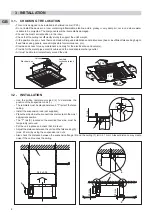
A - Montage / Installation
• See the main characteristics in the Technical Instructions (for the "RCC").
• Consult the "Installation instructions" supplied with the control.
• Connection to the unit is made using at least 0.75 mm
2
min. cable (1.5 mm
2
max.) via terminal strip X2 (terminals 1 to 9)
of the printed circuit board located in the electrical box.
• The cables used must comply with the insulation requirements for the voltage used (230V).
This information relates above all to the sensor input of the automatic control connected to the 230V supply.
• The temperature adjustment range can be limited by means of the mechanical limit stops located on the control knob.
Wall
mounting:
• Secure the unit at a height of approximately 1.5 m from the fl oor in a location representative of normal convection currents,
while avoiding:
- wall which are poorly insulated or liable to vibrate,
- the proximity of parasitic heat sources (sunshine, heating appliances, lamps, fi replaces, televisions, etc.),
- currents of air from doors or windows,
- sheltered locations such as shelves or behind curtains,
- near electrical outlets.
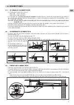
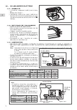
• For manual control 70250076, check and modify as required the ventilation selection jumper connection SR depending
on the appliance (see below).
• For automatic control (70250051 and 70250052), check and modify as required the settings on DIP switches 1 to 5
(located inside the control) depending on the application (refer to the indications below and the controller’s technical
manuals).
Terminal strip
X4 "VALVES"
Terminal strip
X2 "CONTROL"
Valve
Position of the SR bridge located inside the controller:
- on SR1
= Permanent ventilation.
- on SR2 (Auto) = Ventilation actuated with the valve.
CWX
"2-pipe"
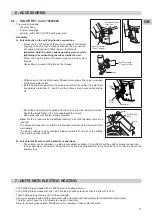
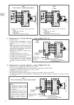
B - Connections with manual remote control - code 7025076 ("RAB 30")
• For CWX "2-pipe", "2-pipe c electric heating" and "4-pipe".
•
Manual selection of the operating mode (heating or cooling).
• Control by action on the 230V "On/Off" valve.
• Permanent or slaved ventilation.
Operating switch
with fan speed selection
Temperature setting
knob
Heating / cooling selector switch
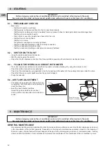
Operating switch with fan speed selection
Temperature setting knob
Ventilation on indicator light
Cooling on indicator light
Heating on indicator light
70250051 / 70250052