13
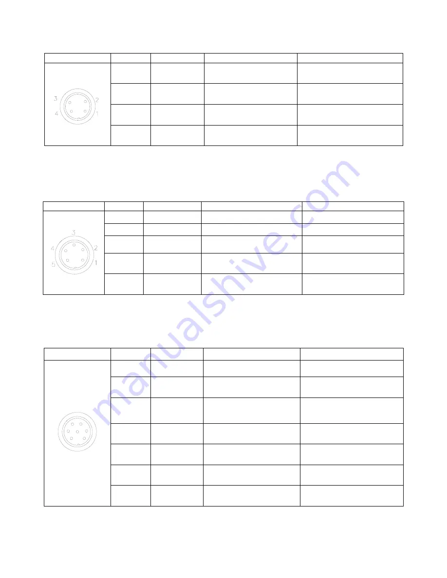
3.2.2 Four Pin Socket “Pin Out” -
the following list describes the pin function of the four-pin socket.
Four-pin socket
Pin No.
Pin name
Instruction of pins
Application
1
Min4
Main signal input 4
Now it’s used to connect to
“START/STOP” switch.
2
GND
Ground of power supply
3
Min1
Main signal inputting 1
Now used to reset (ORG) signal
4
Min2
Main signal inputting 2
Now used to connect emergency
stop switch
Note:
*If a special function is required, the input and output signal can be set again.
3.2.3 Five Pin Socket “Pin Out”
- the following list describes the pin function of the five-pin socket. The socket
can connect with a photo-electricity switch etc.
Five-pin socket
Pin No.
Pin name
Instruction of pins
Application
1
24VDC
“+” power supply
Output signal
2
GND
Ground of power supply
3
Min3
Main signal inputting 3
connect to sensor, such as
photoelectric switch
4
Ein13
External input 13
Used as alarm when
lacking fluid, etc.
5
Ein14
External input 14
Used as alarm when
lacking fluid, etc.
Note:
*If a special function is required, the input and output signal can be set again.
3.2.4 Seven Pin Socket “Pin Out” -
the following list describes the pins function of the seven-pin socket. By the
socket, it can control the external device.
Seven-pin socket
Pin No.
Pin name
Instruction of pins
Application
1
2
3
4
5
6
7
1
24V
“+” power supply
Output signal
2
GND
Ground of power supply
3
Mout1
Main signal output 1, the
current is less than 0.5A
Feeding signal
4
Mout4
Main signal output 4, the
current is less than 0.5A
Cylinder movement signal
5
Min1
Reset and return to the zero
position
Reset (ORG) signal
6
Mout2
Main signal output 2, the
current is less than 0.5A
Output working state signal
7
Mout5
Main signal output 5, the
current is less than 0.5A
Effective as pulse signal
inputted
Note:
*If a special function is required, the input and output signal can be set again.
Содержание TSR2000 Series
Страница 1: ...1 TSR2000 Series 3 Axis Dispensing Robot Hardware Instruction Manual Version 1 3 ...
Страница 12: ...12 3 2 I O Socket Instruction 3 2 1 Circuit Diagram of I O Socket Inside Inside ...
Страница 15: ...15 3 3 2 Circuit Diagram of DB37 ...
Страница 24: ...24 5 MOUNTING AND BRACKTRY 5 1 Tool Plate Valve Mounting Bracket 5 2 Base Plate Product Mounting Plate ...


