background image

10 


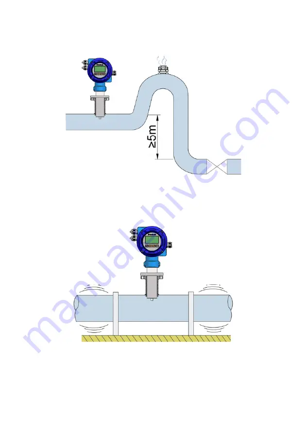
4.5 Aeration 

If there is a point where the difference in level is higher than 5 m an air inlet valve should be 
installed after the sensor to avoid a vacuum effect that could damage the sensor. 

4.6 Vibrations 

Vibrations of the pipes should be avoided by anchoring the pipe before and after the sensor.                   

The vibration level should be less than 2.2 g in the range of 20 -150 Hz according to IEC 068
-2-34.       

Содержание FLOMAT Series

Страница 1: ...R MI FAMX4 Rev 1 English version Series FLOMAT Sensor FLOMAT FX Converter MX4 Instructions manual The art of measuring...

Страница 2: ...nd safety with no obligation to update this manual Make sure this manual goes to the end user Keep this manual in a place where you can nd it when you need it In case of loss ask for a new manual or d...

Страница 3: ...7 Magnetic elds 11 4 8 Temperature 11 5 MOUNTING 12 5 1 Pipe adaptor mounting 12 5 2 Sensor mounting 14 5 3 Tightening torque 14 5 4 Electronic converter connection 14 5 5 Electronic converter program...

Страница 4: ...ds to access the menus 27 6 INSTALLATION PARAMETERS 29 6 1 Language 30 6 2 Sensor factor 30 6 3 Converter factor 30 6 4 Nominal diameter 30 6 5 Diagnosis 30 6 5 1 Parameters 31 6 5 2 Simulator 31 6 5...

Страница 5: ...7 8 Modbus 42 8 SERIAL NUMBER 42 9 SOFTWARE VERSION 42 10 WORKING SCREEN 42 11 STARTING CURRENT 43 12 ASSOCIATED SOFTWARE WINSMETER MX4 44 12 1 USB cable connection and drivers installation 44 12 2 Po...

Страница 6: ...o the magnetic field sense this voltage V 2 RECEPTION The FLOMAT electromagnetic flowmeters are supplied conveniently packaged for transportation together with their instruction manual for installatio...

Страница 7: ...run that guarantees that the pipe is always completely full and where there is a fully developed turbulent flow profile follow indications on point 4 2 Avoid high points of the pipes where air pockets...

Страница 8: ...nts that can disturb the ow pro le such as elbows diameter changes etc Depending on the element the minimum necessary distances upstream from the sensor are shown on the next page BS 1042 2 2 1983 sta...

Страница 9: ...Several 90 coplanar bends Fully opened plug valve Fully opened butter y valve 90 elbow Several 90 non coplanar bends T accessory Total angle convergent 18 to Total angle divergent 14 to 28 Minimum dis...

Страница 10: ...lve should be installed after the sensor to avoid a vacuum effect that could damage the sensor 4 6 Vibrations Vibrations of the pipes should be avoided by anchoring the pipe before and after the senso...

Страница 11: ...oided 4 8 Temperature In open air installations it is recommended to install a protection to avoid direct sun light on the owmeter With thermally insulated pipes DO NOT insulate the sensor High temper...

Страница 12: ...For the smallest pipe diameters DN40 50 65 the pipe adaptor is supplied welded to a short length of pipe with a T form For this type just couple it to the pipe by welding or gluing in the case of PVC...

Страница 13: ...t of the label Once the pipe adaptor is placed into its nal position where the label was cut must coincide with the outer diameter of the pipe This ensures that the measuring electrodes penetrate far...

Страница 14: ...us to inform about the suitable sensor length The axis of the pipe adaptor should be perfectly perpendicular to the pipe axis 5 2 Sensor mounting Once the pipe adaptor is mounted place the at seal in...

Страница 15: ...gible zero offset Pulse and current output proportional to the ow rate and user programmable Relay outputs user programmable as ow rate alarm or status Local and remote mounting Easy exchange with oth...

Страница 16: ...with outside diameters between 3 5 mm and 10 mm To connect the cables peel the outside insulation to free the inner cables It is recommended to put a terminal at the ends of the wires to avoid loose e...

Страница 17: ...is the same as marked on the label of the converter Terminal Power supply AC Power supply DC 8 Earth NC 9 Neutral 10 Phase It is very important to connect the mains earth to the instruments with AC po...

Страница 18: ...any way and therefore they must be installed externally as required in the application taking into account the limitations of the characteristics of such contacts In the case of having inductive load...

Страница 19: ...hich means that the receiving device must be passive or passive which means that the receiver must supply the power for the current loop It is recommended to use a receptor with an input resistance of...

Страница 20: ...The pulse output is opto isolated The terminals are the collector and emitter of a NPN bipolar transistor In the case of using inductive loads in order to protect the output transistor the use of free...

Страница 21: ...ds it should be cut at the breakage point and reworked for the connection at that point 3 1 Preparing the cable The ends of the cable should be prepared as shown in the drawing on next page Special ca...

Страница 22: ...22...

Страница 23: ...with a conductivity higher than 500 S cm cable length can be up to 150 m 3 3 Cable connection to sensor For the sensor connection first loosen the cable gland to allow the cable to slide in it Make s...

Страница 24: ...the ow direction shown in the instrument matches the actual direction please take into account the cables colour scheme according to the gure on page 21 Slide the cover on the sensor neck until it mee...

Страница 25: ...characteristics Working Voltage 250 V Testing Voltage 1000 V Electrical resistance 52 2 km Capacity C C 90 170 pF m C capacity between conductors C capacity between one conductor and the rest connect...

Страница 26: ...crease the digit Into the menu to scroll up Enter To validate the data To enter into installation and programming modes of the converter To exit from an informative text Escape To return to the previo...

Страница 27: ...pter 7 of this manual From the Reset totalizer option the user can return the totalizer to zero When exiting the menu the totalizer will begin to accumulate again Note The Reset totalizer operation re...

Страница 28: ...screen to enter the new password appears Once entered the new password is asked again to avoid possible inadvertent error If the re entered password does not match the rst one the following error mess...

Страница 29: ...n Left and Up select Installation and then validate with the key Enter In order to access to the Installation menu a password must be entered When accessing the rst time the default password is 0123 F...

Страница 30: ...or In this screen the sensor factor is shown It should coincide with the Fc parameter on the sensor label 6 3 Converter factor The electronic converter factor is shown It should coincide with the Fe p...

Страница 31: ...liquid should always be higher than 20 S cm The third row shows the differential voltage value on the electrodes Vdif This voltage appears in some cases where chemical reactions are created on the su...

Страница 32: ...ess again the Escape key until the working screen 6 5 3 Mains frequency If the power supply of the converter is AC the following screen will appear Normally Automatic should be selected In this case t...

Страница 33: ...rs Once the password is entered the rst screen allows to choose between the different programming options 7 1 Language The language in which all the menus will be displayed can be chosen With the keys...

Страница 34: ...ically change to one decimal and when the ow rate is higher than 9999 9 the indication will be done without decimals If one decimal is selected the ow rate indication will have a maximum of one decima...

Страница 35: ...e lower zone of the scale The maximum allowed value for the cut off is the equivalent to a liquid velocity of 1 m s 7 4 1 Empty pipe Detection can be programmed in two different ways In the event that...

Страница 36: ...horter integration time will provide more or less stable readings and will also affect the response time to small variations of ow rate The integration time is selected in seconds with a minimum value...

Страница 37: ...a completely full pipe is necessary in order to make an effective adjustment When the option Offset is selected the following screen is shown When the ow rate is stable press the key Enter and the in...

Страница 38: ...the owmeter detects empty pipe 7 5 1 3 Negative ow The relay will change its status when the ow rate changes its sign 7 5 2 Pulse output This output allows to connect the converter to a PLC or remote...

Страница 39: ...s for which we want to get a number of pulses are selected 7 5 2 3 Pulses Then the pulses per unit of volume that we will obtain at the output are selected 7 5 2 4 Duty Cycle With the duty cycle width...

Страница 40: ...w increases 7 5 3 3 Current calibration for 4 and 20 mA The MX4 converter is delivered with the current output already calibrated If you want to correct a derive of the 4 or 20 mA current values becau...

Страница 41: ...lecting Totalizer is the following If Null is selected the totalizer remains unchanged If Increase is selected the totalizer will add the amount of uid passing through the owmeter and if you select De...

Страница 42: ...direction The programming will be Positive ow rate action Increase Negative ow rate action Increase The totalizer will indicate the volume corresponding to the sum of both products Note To reset the t...

Страница 43: ...TARTING CURRENT It may happen that the chosen power supply can not provide the required current for the equipment to operate properly In this case an information message will appear indicating this si...

Страница 44: ...connection and drivers installation Extract the les from the winsmeterMX4 zip to a new system folder Execute the Setup exe le and follow the steps for the installation In order to connect the convert...

Страница 45: ...l number Then click Open Once the port is open the button Open in the Installation and Programming sections activates Connect the USB cable at one end to the converter and at the other to the computer...

Страница 46: ...assword The default password is install and it can be changed using the boxes on the right of the Installation section Likewise to change the data contained in the Programming tab it is necessary to e...

Страница 47: ...ed To enter the Installation window just click the corresponding tab In the installation window the parameters that adapts the converter to a sensor and to a certain installation can be con gured To t...

Страница 48: ...is screen the different functions of the equipment can be programming As in the previous paragraph to program this data to the MX4 converter press the Send button The message Saving program will appea...

Страница 49: ...s of the equipment can be registered in a le The time between samples as well as the start and end time of the record can be selected When the Register button is pressed the screen that allows to name...

Страница 50: ...50 The created le has CSV format which can be viewed directly with a spreadsheet...

Страница 51: ...eal time ow rate totalizer and velocity values as well as the current value of the analog output and the status of the relay outputs It is an intuitive tool to verify that the instrument has been inst...

Страница 52: ...tec uid com downloads To update the equipment go to menu Firmware Update and a screen with the button File will appear Pressing this button system can be accessed The downloaded le has to be searched...

Страница 53: ...4 20 mA Active or passive galvanically isolated from the power supply Pulse output Optoisolated NPN bipolar transistor Vmax 30 VDC Imax 30 mA Maximum frequency 5000 Hz Minimum frequency 0 01 Hz Relay...

Страница 54: ...OM instructions manual that can be downloaded from Tec uid S A website 14 MAINTENANCE Sensor Electrode cleaning is recommended in installations where signi cant build ups or sedimentation occur Cleani...

Страница 55: ...ubject to conformity assessment are considered outside the scope of the directive and therefore they have not the CE mark according to pressure directive These devices are subject to applicable sound...

Страница 56: ...56 16 DIMENSIONS All dimensions in mm DN A FM 40 450 113 5 328 500 1000 218 5 433 1200 2000 368 5 583 FM is the minimum length to remove the instrument from the pipe FLOMAT FX R 2...

Страница 57: ...57 FM is the minimum length to remove the instrument from the pipe DN A FM 40 450 113 5 328 500 1000 218 5 433 1200 2000 368 5 583 FLOMAT FX TF flange and standards All dimensions in mm...

Страница 58: ...58 DN A FM 40 450 113 5 328 500 1000 218 5 433 1200 2000 368 5 583 FLOMAT FX remote converter version All dimensions in mm FM is the minimum length to remove the instrument from the pipe...

Страница 59: ...59 MX4 REMOTE CONVERTER wall mounting MX4 REMOTE CONVERTER pipe mounting Fittings are supplied for mounting on pipes of 53 max Use DIN 571 or similar screws depending on installation...

Страница 60: ...ension Verify that the owmeter is adequate for this application The instrument is misaligned Align according to point 5 2 on page 14 The ow rate displayed is 0 Coil cable disconnected Connect the cabl...

Страница 61: ...e with upwards ow Blown fuse Change the fuse Not enough current from the power supply Change the power supply The analog output gives always 4 mA or 20 mA Current output range not properly programmed...

Страница 62: ...62 ANNEX A...

Страница 63: ...ic substances The devices sent for repair must enclose the corresponding form which can be lled in via website from the same After Sales section Warranty for repaired or replaced components applies 6...

Отзывы: