Receiver
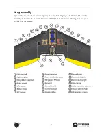
Place the R/C receiver in the designated left electronics compartment and feed all wires through either of
the two channels - recommended to use the rear one.
Feed the antenna coax through the outlet cut and tape it in place, or use the unused antenna hole for a
more rigid antenna installation.
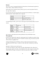
Set up the radio for delta wing mixing. The receiver should be connected as follows on a radio that outputs
TAER (Throttle Aileron Elevator Rudder) channel arrangement:
Channel 1
Throttle
Channel 2
Wing servo left / Aileron
Channel 3
Wing servo right / Elevator
On the TBS TANGO FPV remote, you can limit the travel range by using the following settings on the servo
channels:
Source
Wing [L or R]
-
Mid. Pos.
+20%
tad up elevon pitch
Max. Pos.
+60%
limit travel range up
Min Pos.
- 60%
limit travel range down
Direction
[Normal or reverse]
-
Also to make the stick movements less sensitive, add 60% aileron expo and 50% elevator expo.
TBS equipment
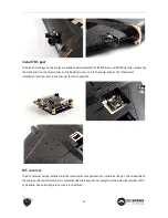
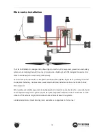
Both electronics compartments are layed out to provide ample space for installation of our FPVision, Wing
layer, and Core Pro boards, with space for the required BST- and receiver-wiring. Screw holes are provided
to fasten the boards using M3x6 screws.
Installing the TBS Wing Layer and TBS FPVision is done in a minutes. Even power to the ESCs can be
provided by the TBS FPVision layer, or in addition to a SBEC enabled ESC, all protected by the TBS Wing
layer.
Wing layer, FPVision and CrossFire micro
This combination provides an excellent build that provides a 800mW-capable Unify Pro 5G8 with twin
camera switcher, a digital current sensor, a fully customizable OSD to inform the pilot of the status of the
aircraft, TBS DCDC V2 to power to the servos and a direct servo output from CrossFire micro receiver.
21
Содержание CAIPIRINHA II
Страница 9: ...Underside of the wing assembly 9 ...

