background image

21 

9.5 Removal of manifold to clean pilot orifice  


With reference to Section 10.1, firstly disconnect the 2 electrical connectors from the coils.


With a 5mm Allen Key 

remove the 2 socket head cap screws retaining the manifold assembly onto the valve body.  


The pilot orifice (item 6) can now be inspected for contamination and cleaned. 


Refit the O rings in the correct position. Assemble the manifold back onto the valve.  The 2 socket head cap 
screws should be refitted with a thread locking liquid applied to the thread and tightened to a torque of 20.3 Nm 
(15 lbft). 
 

9.6 Removal of pressure relief valve and bypass valve from flow control slice  


With reference to Section 10.2, remove the bypass valve unscrew cap (6) and remove along with the bonded seal 
(9) and spring (7).  Using long nose pliers remove the spool (4) and bypass valve body complete with “O” rings. 
Clean and rebuild. 


To remove the Pressure Relief Valve unscrew the complete valve from the slice and inspect the seat for 
contamination, clean and replace. 
 

9.7 Adjusting the pressure relief valve. 


To check the relief valve setting place an in line pressure gauge in the supply hose to the valve.  Remove both 
hoses from the bed chain hydraulic motor and blank both hose ends. ( 3/8” BSP blanking plug for the hose fitting).  
Start the tractor and operate the bed chain with the bed chain speed control in its mid position.  The pressure 
shown on the gauge should be 120 bar.  The pressure setting should remain the same throughout the whole 
range of bed chain speed. 


To adjust the bed chain pressure remove the cap (item 21 Section 10.2) over the relief valve.  To increase the bed 
chain pressure setting, turn the grub screw (item 20) clockwise until the desired setting is achieved.  Replace the 
cap. 
 

9.8 Pressurising valve maintenance. 


To check the operation of the pressurizing valve.  Unscrew the valve assembly form the Outlet Cap (item 2  
Section 10.5) and check the ball is seated correctly and free to move. 
 

9.9 Leaks – seal replacement 


Remove the hoses and electrical connections from the valve.  Remove the valve on its mounting plate from the 
machine.  Take the mounting plate off the valve and thoroughly clean the valve of dirt and debris before stripping 
the valve. 


To split the valve to replace interface seals undo the long studs through the valve and separate individual slices. 


Replace the damaged seals and reassemble the valve.  Fitting of O rings not obtained from manufacturer may 
lead to repeated failures as specific high quality grade O rings are used to seal the valve 


The studs should be tightened to a torque of  13.5 Nm (10 lb ft). 

 
9.10  Specific torque settings 


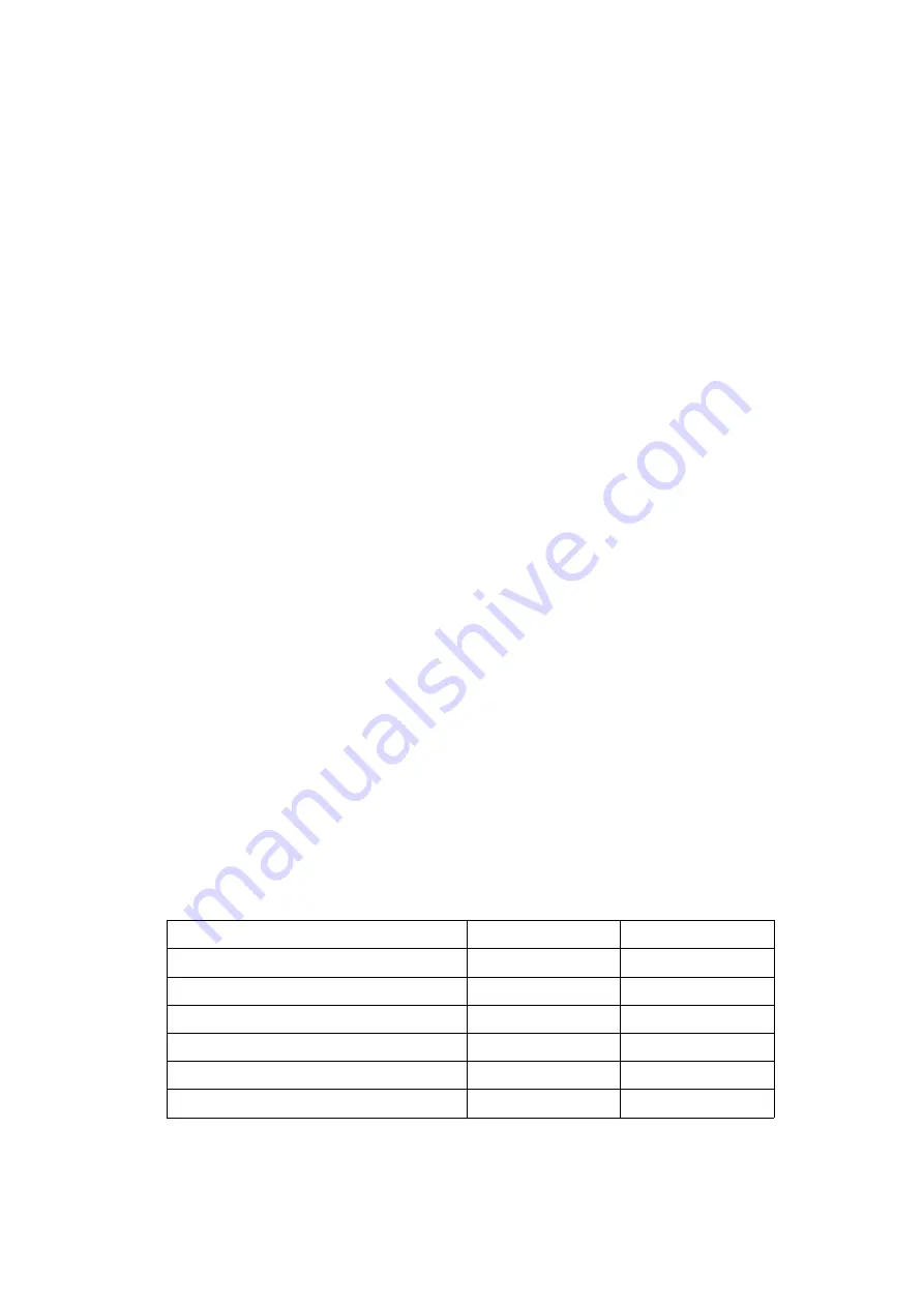
Torque Setting (Nm)  Torque Setting (lb ft) 

Long studs through valve 

13.5  

10  

Closure plate socket head cap screws 

13.5  

10  

Manifold socket head cap screws 

20.3  

15 

Cartridge valve assemblies 

27.1  

20 

End cap unions (Inlet/Outlet) 1/2” BSP 

70-75 

52-55 

Slice port unions 

70-75 

52-55 

Table 9.10 

Torque Settings 

Содержание Tomahawk 808S

Страница 1: ...lectronic System Details Issue 11 08 Tomahawk 808S From Serial No 2000 Tomahawk 8080 From Serial No 3800 Tomahawk 9090 From Serial No 1600 Tomahawk 1005 From Serial No 1501 Tomahawk 1010 From Serial No 3501 Instruction Book Parts List ...

Страница 2: ...r HEALTH AND SAFETY AT WORK Our equipment is designed so as to conform with current Health Safety Regulations and therefore poses no significant hazard to health when properly used Nevertheless in the interests of all concerned it is essential that equipment of our manufacture is used in accordance with the instructions that are supplied or are available from our Technical Staff Legislation requir...

Страница 3: ...Valve Parts List 8 SECTION 4 Hydraulic Hoses Parts List 12 SECTION 5 Electronic Control Identification 14 SECTION 6 Control Box Functions 15 SECTION 7 Circuit Diagrams 16 SECTION 8 Solenoid Valve And Controls Trouble Shooting 18 SECTION 9 Solenoid Valve And Controls Repair And Adjustment 20 SECTION 10 Solenoid Valve And Controls Parts List 23 ...

Страница 4: ... mounting bolts unbolt the box and refit reversed then replace the lid making sure the seal is correctly positioned It should be remembered that structural members of the cab must not be drilled or welded and thus some modification of the mounting bracket may be required Place the electric control unit in the cab and slot into the control box mounting bracket Provided with the controls is a supply...

Страница 5: ...5 NOTES ...

Страница 6: ...and rebuild With reference to Section 3 2 remove the pressure relief valve by unscrewing the complete valve from the slice and inspect the seat for contamination clean and replace 2 3 Bed chain speed control stops working on full or part bed chain speed Possible causes Flow control spool jammed open by contamination Solution Remove the valve guard from the front of the machine Slip the rubber shie...

Страница 7: ... body making sure the O ring remains outside the slip ring Reassemble the cable back onto the spool and refit the cap at the bottom of the valve IMPORTANT To ensure correct and reliable operation OEM components including O rings must be fitted during any overhaul of the valve failure to do so may lead to repeated failures as specific high quality grade O rings are used to seal the valve Remove the...

Страница 8: ...81 1 1 1 Control adapter kit 1 2 5 6 1 Actuator standard HYD5065 3 4 4 Actuator TMC Flow control HYD5066 1 1 1 2 Cable 3 5 meters long HYD5076 HYD5185 4 5 5 3 Actuator RDB HYD5184 4 5 5 Bent Handle HYD5182 4 5 5 Plain nut M10 FAS2303 4 5 5 Standard knob HYD5176 HYD5166 3 4 4 Round knob HYD5165 HYD5165 1 1 1 Actuator boot HYD5183 4 5 5 4 Adapter kit valve end HYD5079 HYD5186 3 4 4 5 Rubber sleeve H...

Страница 9: ... FAS2652P 4 4 4 Locknut M10 FAS2333 FAS2333 4 4 4 12 Divertor valve HYD5085 HYD5085 1 Bolt M6 x 70 FAS9614P FAS9614P 2 Washer M6 FAS2342P FAS2342P 4 Locknut M6 FAS2331 FAS2331 2 13 Hand valve mounting SC3461 SC3461 1 Setscrew M10 x 20 FAS2652P FAS2652P 4 Lock nut M10 FAS2333 FAS2333 4 14 Cable actuator mount T8080 SC3064 SC3717 1 Cable actuator mount T8080S TC SC3209 SC3717 1 1 Stud M6 x 195 FAS91...

Страница 10: ...10 3 2 CABLE CONTROL VALVE PARTS SEALS ...

Страница 11: ...w Outlet Ref Description cover detent spring 4 position valve valve control cover O ring with internal diameter of 3 69 mm and a material diameter of 1 78mm is specified by 3 69 x 1 78 Anti extrusion ring with internal diameter of 7 29 mm and a material thickness of 1 40mm is specified by 7 29 x 1 40 1 O ring 3 69 x 1 78 2 2 2 2 3 2 O ring 12 42 x 1 78 3 3 3 3 1 3 3 O ring 15 60 x 1 78 1 4 O ring ...

Страница 12: ...12 SECTION 4 HYDRAULIC HOSES PARTS LIST ...

Страница 13: ...04 2 L Divertor valve HYD5085 HYD5085 HYD5085 1 x BSP M M unions HYD1114 4 x 3 8 BSP M M unions HYD1115 2 Bonded seal BSP HYD4204 6 M Seg ram hose inner HYD5085 HYD5085 HYD5085 1 N Seg ram hose outer HYD2048 HYD2048 HYD2048 1 P Divertor valve hose HYD2048 HYD2048 HYD2048 2 Q Valve to T piece HYD2064 HYD2064 2 1 4 BSP T piece M M M HYD1921 2 R Chop unit side hose HYD2065 HYD2065 2 1 4 BSP M F 90 El...

Страница 14: ... Junction Box Grey Cable Enters Side Small Domed Buttons Chute Symbols Only Figure 5 3 Previous Design Small Domed Buttons Grey Cable Enters Top Control Box Junction Box NOTE All current design control desks have a serial number on the base of the control desk which can be identified through the aperture of the steel mounting plate Please quote the serial number when entering into any corresponden...

Страница 15: ...either of the two directional buttons 6 3 OVERLOAD PROTECTION Along with the in line fuse 7 5 amp the electronic controls also have a built in overload short circuit protector When the fuse fails the red LED on the fuse holder will illuminate When the protection device activates due to an overload the control box will not operate and the LED will flash In order to reset the device the control box ...

Страница 16: ...16 SECTION 7 CIRCUIT DIAGRAMS 7 1 SMALL DOMED BUTTONS ...

Страница 17: ...17 AS FITTED TO VALVE WITH INDEPENDENT SPEED CONTROL SLICE ON OFF DL1115 OFF ON DL1115 7 2 LARGE RAISED FLAT BUTTONS AS FITTED TO VALVE WITH COMBINED SPEED CONTROL FORWARD SLICE ...

Страница 18: ...jammed in machine or drive to bed chain failed b Hydraulic Motor failed or seized c Failure of the wiring to the circuit board the connections to the potentiometer within the control box or poor connections in the connector between the control box and machine cable d Pilot orifice blocked in manifold of solenoid slice controlling bed chain forward and reverse Solution a Check Bed chain and drive m...

Страница 19: ...ass Valve in the flow control slice does not allow it to close resulting in the oil dumping to tank starving any oil flow to the motor h Dirt or contamination in the Pressure Relief Valve in the flow control slice does not allow it to close resulting in the oil dumping to tank starving any oil flow to the motor i Dirt or contamination in the Pressurising Valve in the outlet cap does not allow it t...

Страница 20: ...n the control box is varied from stop to full flow it should be possible to measure the following voltages on the connector in the middle of the junction box circuit board cable labelled 3 12v 4 5v 5 0v 6 variable 0 to 5v If only the variable voltage has failed then the potentiometer in the cab control box may have a faulty connection or has failed Check for good connections if none are apparent r...

Страница 21: ...d position The pressure shown on the gauge should be 120 bar The pressure setting should remain the same throughout the whole range of bed chain speed To adjust the bed chain pressure remove the cap item 21 Section 10 2 over the relief valve To increase the bed chain pressure setting turn the grub screw item 20 clockwise until the desired setting is achieved Replace the cap 9 8 Pressurising valve ...

Страница 22: ...ontrol panel by following the instructions below Neither the control box or junction box needs to be opened 1 With the control box off and with reference to figure 6 1 hold the bed chain forward raise knives and ON buttons together for 8 seconds until both LED s are ON Set up mode will now be shown by the ON LED and Bed Chain LED flashing alternately 2 Set bed chain speed control dial to 0 5 reduc...

Страница 23: ...23 SECTION 10 SOLENOID VALVE AND CONTROLS PARTS LIST 10 1 DOUBLE ACTING SLICE ...

Страница 24: ...24 10 2 PROPORTIONAL SOLENOID SLICE INDEPENDENT BED CONTROL 10 3 PROPORTIONAL SOLENOID CARTRIDGE 10 4 OUTLET END CAP 10 5 PRESSURISING VALVE ASSEMBLY ...

Страница 25: ... control valve seal kit HYD5317 1 1 1 10 7 SOLENOID VALVE PARTS COMBINED SPEED CONTROL FORWARD SLICE Ref Description Part No RH SC DC TC A Cover Bed control end HYD5406 1 1 1 1 B Relief valve assembly HYD5407 1 1 1 1 C Double acting slice spring return HYD5192 2 3 4 5 D Flow control slice HYD5404 1 1 1 1 E Bed reverse slice HYD5405 1 1 1 1 F Outlet Cover HYD5315 1 1 1 1 G Flow dividing slice HYD51...

Страница 26: ... SC HYD5401 3 Valve DC HYD5402 4 Valve TC HYD5403 Note Valve mounting plate and fasteners are as for solenoid valve with independent speed control Ref Description Part No RH Chute SC Chute TC DC 1 Electric Valve HYD5094 1 2 Electric Valve HYD5095 1 3 Electric Valve HYD5096 1 4 Valve mount bracket SC3539 1 1 1 Setscrew M8 x 16 FAS2625P 4 Washer M8 FAS2343P 4 ...

Страница 27: ...3516 SC3516 SC3516 18 10 Control box socket SC3515 SC3515 SC3515 1 M4 x 16 Pan Head FAS2430S 4 M4 Locknut FAS2329S 4 11 Support Bracket SC3538 SC3538 SC3538 1 M4 x 16 Pan Head FAS2430S 4 M4 Locknut FAS2329S 4 Junction Box Assembly SC3557 SC3556 SC3542 1 12 Crimp contacts SC3519 SC3519 SC3519 18 13 Cable socket SC3518 SC3518 SC3518 1 14 18 Core cable assy 4m SC3522 SC3522 SC3522 1 18 Core cable ass...

Страница 28: ...racket SC3538 SC3538 SC3538 1 M4 x 16 Pan Head FAS2430S 4 M4 Locknut FAS2329S 4 Junction Box Assembly SC3583 SC3582 SC3581 1 12 Crimp contacts SC3519 SC3519 SC3519 18 13 Cable socket SC3518 SC3518 SC3518 1 14 18 Core cable assy 4m SC3522 SC3522 SC3522 1 Standard 18 Core cable assy 5m SC3592 SC3592 SC3592 1 Optional 18 Core cable assy 7m SC3594 SC3594 SC3594 1 Optional 15 PCB Large Controls SC3575 ...

Отзывы: