background image

408-9279 

Rev F


of 7


4.  Make sure the ratchet is released. Squeeze the tool handles together and allow them to open fully. 

5.  Rotate the blue plastic locator stop index to the appropriate position. 

  When crimping a 110 Series terminal, rotate the index until the number 

“110” 

appears in the 

uppermost position. 

  When crimping a 187 or 250 Series terminal, rotate the index until the numbers 

“250

-

187”

 appear in 

the uppermost position. 

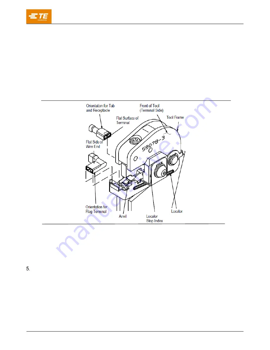
6.  Insert the terminal into the proper crimp section. 

  In-line terminals may be crimped in either in-line section. 

  Flag terminals must be crimped in the flag crimp section (see Figure 4). 

  For in-line terminals, the flat side of the terminal must seat on the locator. 

  For flag terminals, the flat side of the wire end must face outward and the mating end must seat on 

the locator. 


Figure 4 

7.  Squeeze the tool handles sufficiently to hold the terminal firmly in place without deforming it. 

8.  Insert a properly stripped wire into the barrel of the terminal. 

9.  Hold the wire in place and squeeze the tool handles until the ratchet releases. 

10. Allow the tool handles to open fully and remove the crimped terminal. 


MAINTENANCE/INSPECTION 

5.1.


Daily Maintenance 

Remove all foreign particles with a clean, soft brush or a clean, soft, lint-free cloth. Do NOT use materials or 
objects that can damage the dies. If foreign matter cannot be removed easily, or if the proper replacement parts 
are not available, return the dies to your supervisor. 

Make certain the dies are protected with a THIN coat of any good SAE 20 motor oil. DO NOT OIL 
EXCESSIVELY. 

When the dies are not in use, mate them and store in a clean, dry area.    


SAE is a trademark 

Содержание Faston Series

Страница 1: ...DESCRIPTION Each die assembly consists of an upper die crimper and a lower die anvil a retaining screw on the upper die and a hex wrench for securing the lower die to the platform of the hand tool fra...

Страница 2: ...3 135 250 In Line Recpt 520184 520183 1 Dot 5 84 230 250 In Line Recpt 520264 520263 1 Dot 3 43 135 250 In Line Tab 520103 520102 1 Dot 4 19 165 250 Flag Recpt 520129 520128 Plain No Mark 16 14 6 60 2...

Страница 3: ...ket head screw on the die platform clockwise until snug Do NOT overtighten 3 2 Installing Upper Die Assembly 1 Remove the die retaining screw from the die assembly 2 Position the upper die in upper di...

Страница 4: ...f the wire end must face outward and the mating end must seat on the locator Figure 4 7 Squeeze the tool handles sufficiently to hold the terminal firmly in place without deforming it 8 Insert a prope...

Страница 5: ...ttened chipped cracked worn or broken areas If damage is evident the dies must be repaired before returning them to service Refer to Section 6 REPLACEMENT AND REPAIR 5 3 Gaging the Crimping Chamber Th...

Страница 6: ...ACEMENT AND REPAIR The parts listed in Figure 7 are customer replaceable A complete inventory can be stocked and controlled to prevent lost time when replacement of parts is necessary Order replacemen...

Страница 7: ...Size Column from 22 16 to 22 18 Relocate several figures to more closely align with applicable text Split original Figure 5 into 2 figures changed references and Figuring numbering accordingly Removed...

Отзывы: