408-1745
4
of 7
Rev
D
4. Activate the power unit to complete the crimp.
5. To complete the other half of the butt splice,
remove and reposition the uncrimped half of the
splice in the nest. Insert the wire and then activate
the power unit to crimp the splice. The completed
terminal or splice should be as shown in Figure 5.
7. INSPECTION/MAINTENANCE
DANGER
Make sure hydraulic pressure is released and power
supply is disconnected before following inspection and
maintenance procedures, unless otherwise specified in
the procedure.
Each crimping head is assembled and inspected
before shipment. It is recommended that the crimping
head be inspected immediately upon its arrival at your
facility, and at regularly scheduled intervals, to ensure
that the crimping head has not been damaged during
handling. Frequency of inspection depends upon the
following: care, amount of use, and handling of the
head; type and size of products crimped; degree of
operator skill; and environmental conditions.
7.1. Cleaning
Remove accumulations of dirt and grease on the
crimping head, especially in areas where dies are
installed and terminals are crimped. Clean the entire
head frequently with a clean, lint-free cloth.
7.2. Visual Inspection
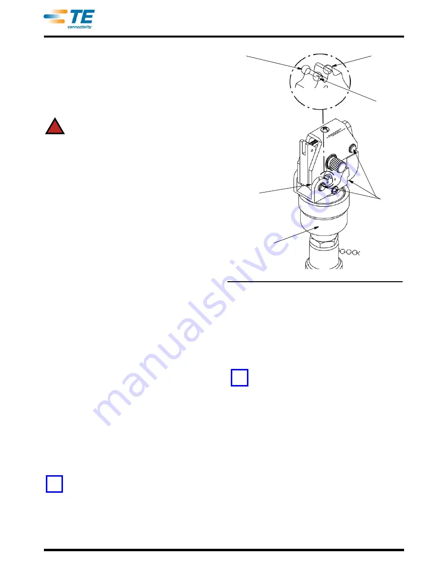
Refer to Figure 6 and proceed as follows:
Chipped
Area
Flattened
Area
Pitted
Area
Check for
Excessive Wear
at all Pivot Points
Check These
Areas for Cracks
Check These
Areas for Cracks
1. Visually inspect die closure surfaces for chipped,
pitted, or flattened areas.
2. With hydraulic pressure released, inspect the
assembled head for nicks, scratches, and cracks.
Inspect for cracks especially at the corners of the
yoke and around the top of the cylinder.
3. Inspect pivot pin holes and latch pin holes for
wear. Replace parts, as needed.
4. Activate power unit. Raise ram to UP position.
Inspect flat and round surfaces of ram for galling
(fretting or wear by friction), cracks, or oil leakage.
Release pressure and make sure that ram retracts
smoothly.
5. If head shows evidence of galling, cracks, oil
leakage, or rough cycling, return the crimping head
to for repairs. (Refer to Section 8, REPLACEMENT
AND REPAIR).
NOTE
I
t is recommended that the head be returned to TE after
every two years (or every 50,000 cycles) for magnetic
particle inspection. Refer to Instruction Sheet 408-9684.
Figure 6
7.3. Die Closure Inspection
Every crimping head die set is inspected for proper die
closure before shipment. However, the dies should be
inspected for excessive wear periodically. Die closure
is accomplished using GO/NO-GO plug gages.
Suggested plug gage design and GO/NO-GO
dimensions are shown in Figure 7.
NOTE
TE neither manufactures nor sells plug gages. Refer to
408-7424 for gaging information.
1. Clean the oil and dirt from the closure surfaces,
and plug gage members.
2. Lock the desired nest in the crimp position and
raise the indenter to the full UP position, as shown
in Figure 8, Detail A.
3. With the indenter positioned at the full UP
position, inspect the die closure using the
appropriate plug gage. Hold the gage in alignment
with die closure and carefully insert, without forcing,
the GO member. See Figure 8. The GO member
must pass completely through the die closure as
shown in Figure 8, Detail B.
4. Try to insert the NO-GO member. The NO-GO
member may enter partially, but must NOT pass
completely through the die closure. See Figure 8,
Detail B.
!
NOTE
i
NOTE
i


