408-9535
Rev D
4
of 6
4. Cycle tool to complete the crimp. Remove crimped terminal or splice.
NOTE
If the splice or terminal sticks in the die after crimping, apply a rocking action to release it.
6.
INSPECTION AND MAINTENANCE
DANGER
Verify hydraulic pressure is released and power supply is disconnected before following inspection and maintenance
procedures, unless otherwise specified in the procedure.
Each crimping head is assembled and inspected before shipment. TE Connectivity recommends that the
crimping head be inspected immediately upon its arrival at the facility of use, and at regularly scheduled
intervals, to ensure the head has not been damaged during handling and use. Frequency of inspection
depends upon the following: care, amount of use, and handling of the head; type and size of products crimped;
degree of operator skill; and environmental conditions.
6.1.
Cleaning
Remove accumulations of dirt and grease on the crimping head; especially in areas where dies are installed
and terminals are crimped. Clean the entire head frequently with a clean, lint-free cloth.
6.2.
Visual Inspection
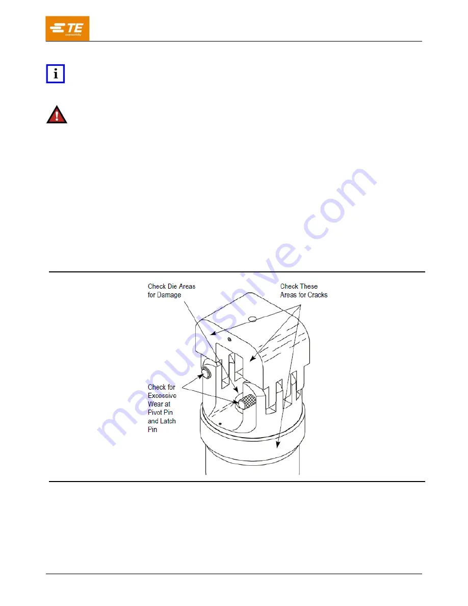
Refer to Figure 4 and proceed as follows:
1. With hydraulic pressure released, inspect the assembled head for nicks, scratches, and cracks.
Inspect for cracks especially at the corners of the yoke and around the top of the cylinder.
Figure 4
2. Inspect pivot pin holes and latch pin holes for wear. Replace parts, as needed.
3. Activate power unit.
Raise ram to “UP” position.
Inspect flat and round surfaces of ram for galling
(fretting or wear by friction), cracks, or oil leakage.
Release pressure and make sure ram retracts smoothly.


