background image

409- 10065

Rev F

6

of 9

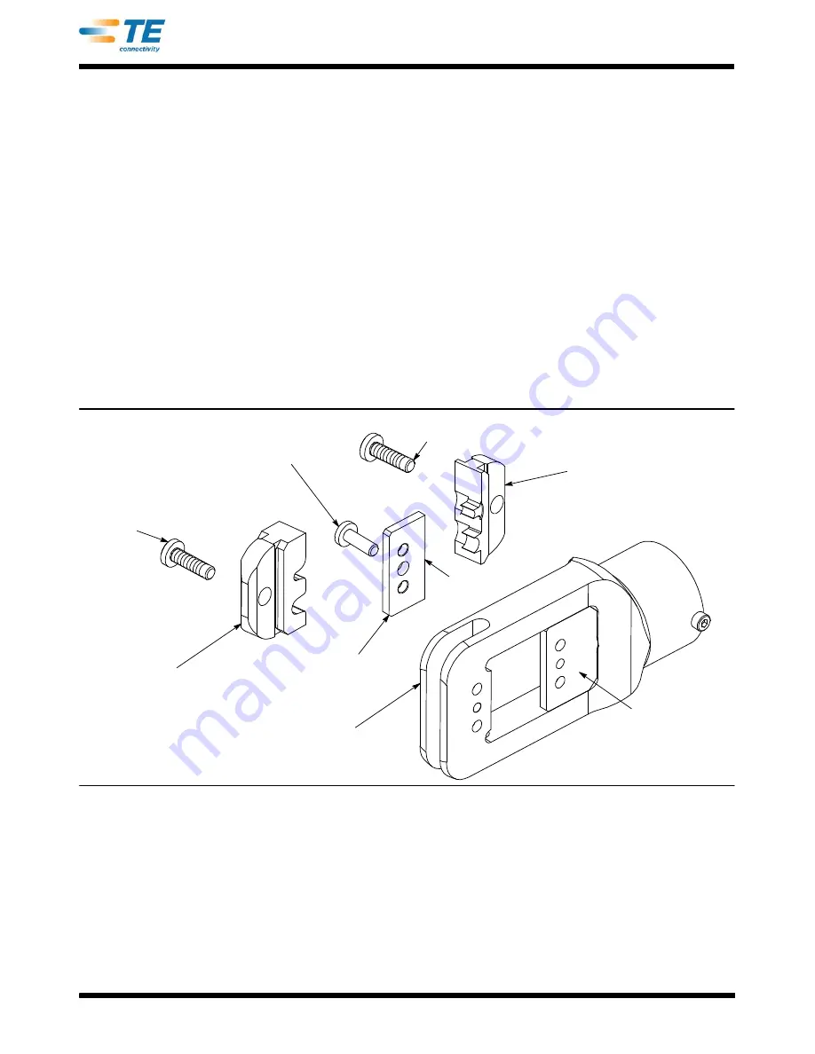
A. Installation of Shouldered Dies

(Figure 2 )

1. Remove the battery from the tool.
2. Remove the two die retaining screws from the crimp head.
3. Remove the ram plate from the moving jaw.
4. Place the upper die in the upper portion of the tool head so that the largest indenter is on the right.
5. Insert the die retaining screw through the upper jaw and through the die. Tighten the screw

just

enough

to hold the die in place. Do

NOT

tighten the screw completely at this time. See Figure 2.

6. Place the lower die in the moving jaw of the crimp head so that the largest anvil is on the right.
7. Place the ram plate on the moving jaw. The chamfers on the corners of the ram plate should be

located adjacent to the die set.
8. Insert the die retaining screw through the ram plate; die set, and the moving jaw. Tighten the screw

just enough

to hold the die in place. Do

NOT

tighten the screw completely at this time.

9. Replace the battery and pulse the trigger to slowly close the crimp head, making sure the anvils and

indenters are properly aligned.
10. When the anvils and indenters are aligned, tighten the retaining screws.

Figure 2

Upper Die

Retaining

Screw

Upper SDE Die

Lower Die Retaining Screw

Lower SDE Die

Moving Jaw

Upper Jaw

Ram Plate

Machine Screw

Chamfer on

Ram Plate

Содержание 1213890-1

Страница 1: ...tenance 9 6 SPARE PARTS 9 7 TROUBLESHOOTING 9 8 RETURN 9 9 REVISION SUMMARY 9 Safeguards are designed into this application equipment to protect operators and maintenance personnel from most hazards d...

Страница 2: ...DANGER DANGER This unit should only be used by trained competent personnel Read and understand the entire manual before using the equipment Always wear approved eye protection when using the equipment...

Страница 3: ...of the manual and drawings to receive instructions Many difficulties can be avoided in this manner When calling the Tooling Assistance Center be ready with the following information 01 Customer name...

Страница 4: ...th Battery Installed Length 349 mm 13 3 4 In Width 60 mm 2 3 8 In Depth 80 mm 3 1 8 In Mass Weight w Battery 1 5 kg 3 4 lb Sound Level 75 dBA at 1 Meter Vibration 2 5 m s2 Hydraulic Oil Shell Tellus T...

Страница 5: ...ch component for evidence of damage that may have occurred in transit If any of the components are damaged file a claim against the carrier and notify TE Connectivity immediately 3 Keep this manual an...

Страница 6: ...w of the crimp head so that the largest anvil is on the right 7 Place the ram plate on the moving jaw The chamfers on the corners of the ram plate should be located adjacent to the die set 8 Insert th...

Страница 7: ...ining screw into the ram plate through the anvil die and moving jaw Tighten the screw just enough to hold the die in place Do NOT completely tighten the screw at this time 7 Install the crimper die in...

Страница 8: ...ys dispose of the old battery pack in an environmentally responsible way in accordance with local waste regulations Where possible please recycle the battery cartridge Contact your local authority for...

Страница 9: ...tery after several minutes to ensure that the battery is holding its charge 2 Use a nonflammable contact cleaner or pencil eraser to clean the the electrical contacts on the battery and crimp tool 3 R...

Страница 10: ...Mouser Electronics Authorized Distributor Click to View Pricing Inventory Delivery Lifecycle Information TE Connectivity 1213890 4...

Отзывы: