T3903
Page 14 of 21
Document Number: DS-000358
Revision: 1.0
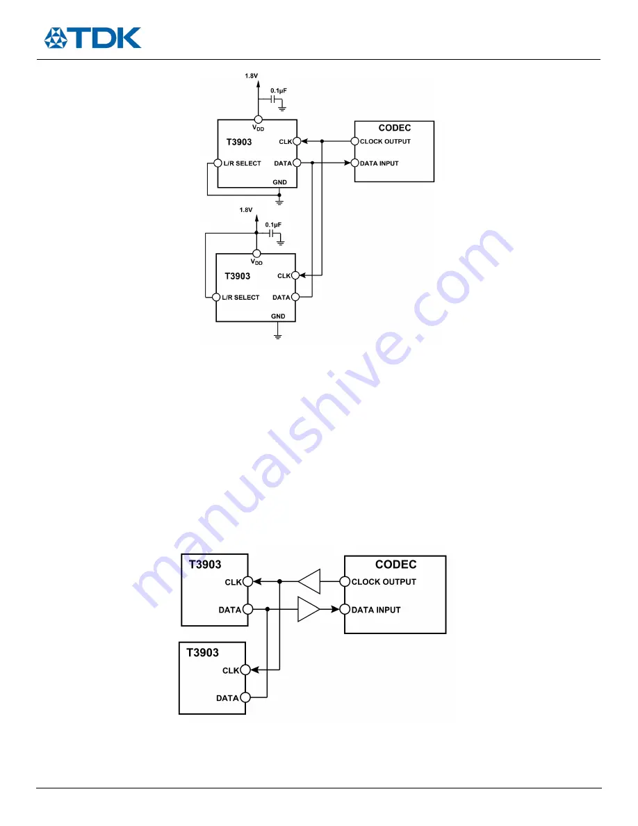
Figure 13. Stereo PDM Microphone Connection to Codec
Decouple the VDD
pin of the T3903 to GND with a 0.1 µF capacitor. Place this capacitor as close to
VDD
as the printed circuit board
(PCB) layout allows.
Do not use a pull-up or pull-down resistor on the PDM data signal line because it can pull the signal to an incorrect state during the period
that the signal line is tristated.
The DATA signal does not need to be buffered in normal use when the T3903 microphone(s) is placed close to the codec on the PCB. If the
DATA signal must be driven over a long cable (>15 cm) or other large capacitive load, a digital buffer may be required. Only use a signal
buffer on the DATA line when one microphone is in use or after the point where two microphones are connected (see Figure 14). The
DATA output of each microphone in a stereo configuration cannot be individually buffered because the two buffer outputs cannot
drive a single signal line. If a buffer is used, take care to select one with low propagation delay so that the timing of the data
connected to the codec is not corrupted.
Figure 14. Buffered Connections Between Stereo T3903s and a Codec
When long wires are used to connect the codec to the T3903, a source termination resistor can be used on the clock output of the
codec instead of a buffer to minimize signal overshoot or ringing. Match the value of this resistor to the characteristic impedance of


