
AN-000158
Document Number: AN-000158
Page 16 of 22
Revision: 1.2
6
ASSEMBLY GUIDELINES, TOLERANCES AND REQUIREMENTS
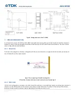
CH101 AND ICU-10201 MOUNTING
The recommended method of placing the CH101 or ICU-10201 in a device is to mount and solder it on its own PCB (FPC, rigid flex or
rigid PCB). This PCBA makes it much easier to control the mounting and assembly of the sensor onto the Acoustic Interface, thereby
decreasing the chances of poor assembly accuracy and reduced acoustic performance.
RECOMMENDED METHOD FOR SENSOR ASSEMBLY AND ATTACHMENT
The assembly method recommended by Chirp for securing the sensor PCBA to the Acoustic Interface is to use liquid adhesive (glue),
because liquid adhesive does not impart additional stress onto the sensor. For all other assembly methods, it is important to verify
that the maximum assembly force is not exceeded post-assembly. For example, while gluing the sensor PCBA to the Acoustic
Interface, an operator may temporarily exceed the maximum assembly force, but before the adhesive finishes curing, this excess
force must be removed. This can be checked by testing the sensor’s operating frequency before and after assembly. The sensor’s
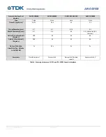
post-assembly operating frequency should not shift beyond a given amount compared to the pre-assembly operating frequency (see
Table 66).
The following is a list of adhesives recommended by Chirp for assembling the PCBA onto the Acoustic Interface:
•
Dymax 9-911 REV A Ultra-light Weld (UV Cure)
For designs using an Acoustic Interface that is separate from the device enclosure, it is also recommended to use glue to assemble
the Acoustic Interface and sensor PCBA subassembly to the device enclosure, because the maximum assembly force requirement
still applies. This method avoids assembly force/stress that can be transferred from the Acoustic Interface and onto the sensor
package.
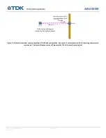
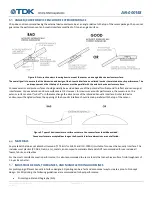
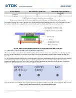
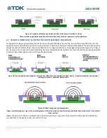
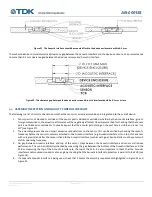
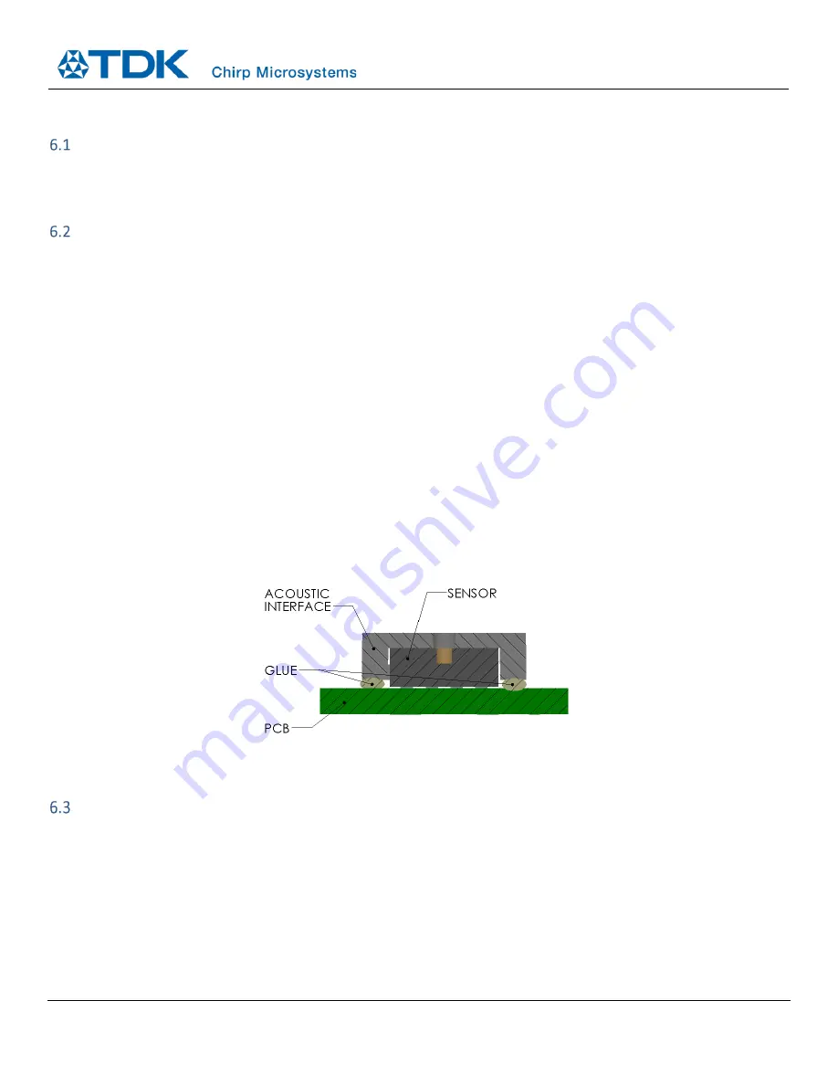
During the assembly gluing process, care should be taken to dispense adhesive in such a way that the adhesive does not flow or wick
into the port hole of the sensor. Therefore, it is recommended to apply the adhesive between the Acoustic Interface and the PCB
(not between the Acoustic Interface and the sensor). A post-cure visual inspection should be conducted to verify that no adhesive
has flowed or wicked into the sensor port hole.
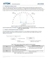
Figure 15. Cross-sectional picture showing where glue should be dispensed for attaching the Acoustic Interface.
The glue should be dispensed between the Acoustic Interface and the PCB and not between the Acoustic Interface and sensor.
MAXIMUM RESIDUAL ASSEMBLY FORCE
To effectively radiate ultrasound into the air, the CH101 and ICU-10201 are manufactured in such a way that the PMUT is not
completely stress-isolated from the package. One integration requirement arising from this feature is that there is a limit to the
amount of residual force that can be applied to the sensor before it results in excessive change in the
PMUT’s acoustic
characteristics. For sensor configurations that are sensitive to operating frequency, such as in Pitch-Catch, the maximum allowed
residual force during operation is 50 grams-force. For all other sensor configurations where the operating frequency is not critical,
the maximum allowable residual force during operation is 150 grams-force. It is acceptable to temporarily exceed these values when
the sensor is not in operation, such as during assembly, as long as the excess force is reduced or removed afterwards (i.e. there are
no excess residual stresses/forces on the sensor after assembly). It is critical that there is no excess residual assembly force above
the maximum allowable value on the sensor once assembly is complete.


