TDK CH101 Скачать руководство пользователя страница 17


AN-000158


Document Number: AN-000158


Page 17 of 22


Revision: 1.2 


Sensor Configuration 

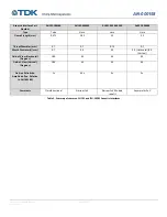
Max Assembly Force (grams-force) 

Max Allowable Frequency Shift Due to 

Assembly (Hz) 

Pulse-Catch 

50 

750 

Pitch-Echo 

150 

1500 

Table 6. Summary of maximum allowable residual assembly force.  

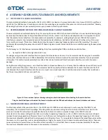
The easiest way to detect when this force is exceeded is to measure the frequency shift from before and after assembly. 

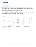
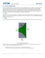
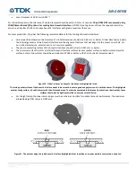
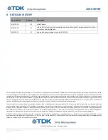
One method of holding the module against the device enclosure while avoiding applying excessive force on the module is to use a 
backplate to transfer the force applied to the module to the Acoustic Interface instead of the sensor (see Figure 16). 


Figure 16. Example of a backplate-based module design to avoid applying excessive force on the sensor. 


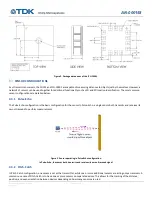
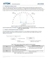
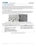
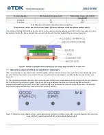
SENSOR-TO-ACOUSTIC INTERFACE ASSEMBLY TOLERANCES 

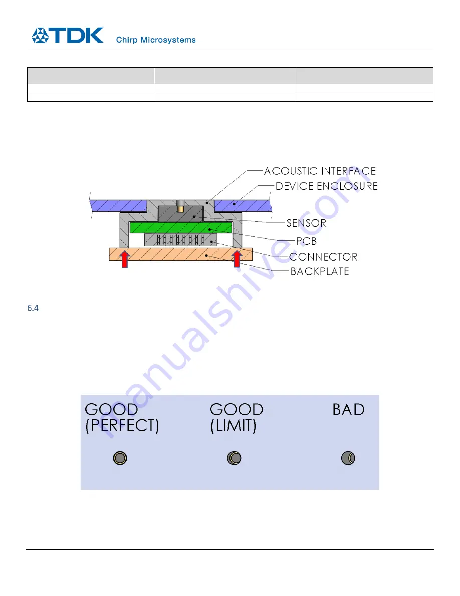
When assembling the sensor and Acoustic Interface together, Chirp recommends the sensor port hole be concentrically aligned to 
Acoustic Interface to within 0.1 mm or better. The sensor port should not be blocked or occluded by the Acoustic Interface (see 
Figure 17)

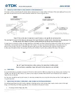
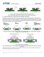
For the Z-dimension assembly tolerance, the only requirement is that there is no gap between the sensor and the Acoustic Interface 
and that their mating surfaces are parallel (see Figure 18). Any gap between the sensor and Acoustic Interface will result in 
unpredictable acoustic performance. In addition, while ensuring no gap between the sensor and Acoustic Interface, the assembly 
force must be below the maximum force limit as discussed in Section 6.3. 


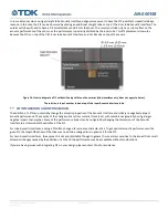
Figure 17. Examples of various degrees of sensor port alignment with the Acoustic Interface, from perfect concentric alignment (left), maximum 

acceptable limit tangent alignment (middle), to bad occluded alignment (right). 

Содержание CH101

Страница 1: ...ons and information herein without notice InvenSense a TDK Group Company 2560 Ninth Street Ste 220 Berkeley CA 94710 U S A 1 510 640 8155 www chirpmicro com Document Number AN 000158 Revision 1 2 Rele...

Страница 2: ...ry part and assembly tolerances material considerations testing and best practices for mechanical integration All dimensions mentioned in this document are in mm unless otherwise specified The informa...

Страница 3: ...c integrated circuit FoV Field of View FPC Flexible printed circuit FWHM Full width half maximum IC Integrated circuit IR Infrared LSB Least significant bits ADC counts MEMS Micro electro mechanical s...

Страница 4: ...D MANUFACTURING GUIDELINES 11 5 PARTICLE INGRESS FILTERS 13 MESHES AND MEMBRANES 13 PIF ACOUSTIC PERFORMANCE IMPACT AND INSERTION LOSSES 14 PIF PLACEMENT 14 PIF INTEGRATION AND OPTIMIZATION 15 6 ASSEM...

Страница 5: ...rom and back to the PMUT known as the Time of Flight ToF is measured by the built in application specific integrated circuit ASIC Using the speed of sound 343 m s at room temperature the system can de...

Страница 6: ...configuration is the basic configuration for the sensor In Pulse Echo a single sensor both transmits and receives its own ultrasound to perform measurements Figure 3 Sensor operating in Pulse Echo co...

Страница 7: ...Revision 1 2 Figure 4 Ultrasonic transceiver sensors operating in Pitch Catch configuration One sensor is set to transmit with all remaining sensors set to receive only The transmitting sensor can st...

Страница 8: ...ies of Acoustic Interface are used with the CH101 and ICU 10201 tubes and horns TUBES Tubes are holes of a specific length and diameter For the CH101 the optimal tube length is 0 475 mm with a diamete...

Страница 9: ...5 5 3 Throat Diameter mm 0 7 0 7 0 75 0 7 Mouth Diameter s mm 0 7 3 0 3 0 5 0 Horizontal 2 0 Vertical Field of View Horizontal Degrees 180 45 45 30 Field of View Vertical Degrees 180 45 45 60 On Axis...

Страница 10: ...ed FoV SEPARATE VS INTEGRATED ACOUSTIC INTERFACE The Acoustic Interface can either be a standalone separate part or it can be integrated into the device enclosure The choice between a separate or inte...

Страница 11: ...ce cannot cut off or otherwise change the dimensions of the intended Acoustic Interface Similar to device enclosures with angled surfaces the opening of the Acoustic Interface should remain parallel w...

Страница 12: ...ptable The sensor contacting surface of the Acoustic Interface should be flat to 0 025 mm or better The minimum surface finish for all critical Acoustic Interface surfaces sensor contact surface tube...

Страница 13: ...cture An example of a nonwoven membrane material would be expanded PTFE Membranes can also be solid thin barriers like polyester or mylar films Figure 12 Representative close up images of the structur...

Страница 14: ...path between the sensor PMUT and the air Chirp s testing has shown that PIFs placed directly on top of the sensor package and right over the port hole generally significantly decrease acoustic perfor...

Страница 15: ...nner Acoustic Interface tube PIF INTEGRATION AND OPTIMIZATION The addition of a PIF can potentially change the acoustic properties of the Acoustic Interface and is likely to negatively impact acoustic...

Страница 16: ...es This method avoids assembly force stress that can be transferred from the Acoustic Interface and onto the sensor package During the assembly gluing process care should be taken to dispense adhesive...

Страница 17: ...ERFACE ASSEMBLY TOLERANCES When assembling the sensor and Acoustic Interface together Chirp recommends the sensor port hole be concentrically aligned to Acoustic Interface to within 0 1 mm or better T...

Страница 18: ...rom undesired features such as edges and gaps see Figure 19 and Figure 20 Because of this wider FoV Acoustic Interfaces are more susceptible to these effects and steps should be taken during assembly...

Страница 19: ...to visually inspect that the annular gold plating on the port hole is visible and is not cut off see Figure 17 2 The assembly process does not impart excessive residual stress on the sensor This can b...

Страница 20: ...amount of sound output into the air thus reducing maximum range Assembly tolerance vs acoustic performance consistency The acoustic performance is the highest when the alignment of all parts in the ac...

Страница 21: ...a larger area For reference a sensor with an omnidirectional Acoustic Interface has a 1m range with a 180 deg FoV to a large flat target Because it is not possible to have a very wide FoV with long ra...

Страница 22: ...ncludes but is not limited to claims or damages based on the infringement of patents copyrights mask work and or other intellectual property rights Certain intellectual property owned by InvenSense an...

Отзывы: