background image

Page 3 of 6 Rev 1  

February 3, 2020 

DRB-480 Handbook

DDA Series Instruction Manual 

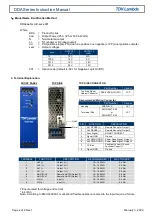
3. Terminal Connecting Method 

Pay attention to the input wiring, if connected incorrectly, the power supply may be damaged. 

  Input must be off when making connections. 

  The output load line and input line shall be separated and twisted to improve noise sensitivity. 

When connecting or removing input and output wires, do not apply stress to the PCB. 

4. Explanation of Functions and Precautions 

(Refer to Full Product Specification for Complete Details) 

4-1. Environmental Specifications 

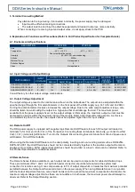
DESCRIPTION 

OPERATION 

STORAGE 

Use 

Indoor 

Temperature 

-40°C - +100°C  

See output derating section 

-55°C - +105°C 

Humidity 

20 - 95% RH, non-condensing 

Altitude 

2000m 

Material Group 

Not applicable 

Pollution Degree 

Class 

Not applicable 

4-2. Input Voltage and Output Ratings 

PART NUMBER 

INPUT 

VOLTAGE 

OUTPUT VOLTAGE 1 

OUTPUT VOLTAGE 2 

MAXIMUM 

OUTPUT 

CURRENT 

MAXIMUM 

OUTPUT 

POWER 

Nominal 

Adjust Range 

Nominal 

Adjust Range 

DDA250N-S1PX-12-001 

9 – 53V 

12V 

3.3 to 15V 

NA 

NA 

20A / NA 

250W / NA 

DDA500N-D2PP-1205-001 

9 – 53V 

12V 

3.3 to 15V 

5V 

3.3 to 15V 

20A / 20A 

250W / 250W 

DDA325N-D2PN-1212-001 

9 – 40V 

12V 

3.3 to 24V 

-12V 

-3.3 to -24V 

14A / 8A 

250W / 75W 

Consult factory for other output voltage combinations. 

4-3. Output Voltage Adjustment  

The output voltage is preset to the nominal value shown on the table above The output can be adjusted within the 
specified range through the trim potentiometers on the front panel of the DDA supply (e.g. Vo1 ADJ and Vo2 ADJ). 
Turning the potentiometers clockwise increases the output voltage. Due to the wide output adjustment range, care 
should be taken to avoid setting the output to a high value that could damage the load. The maximum power 
available from the power supply is fixed. As the output voltage is trimmed up, the maximum output current must be 
decreased to operate within the maximum rating of the module. Refer to the Output Derating section. As this is a 
non-isolated step down converter, the outputs cannot be adjusted higher than the input voltage. 

4-4. Remote On/Off  

The DDA power supply is equipped with negative logic Remote On/Off feature for each DC output rail located on 
terminals 5 (for Vo2) and 6 (for Vo1) of the front panel. Connecting these terminals to Ground [e.g. connect to either 
Vo2(-); Vo1(-) terminals] will Enable / Turn On the Outputs. Disconnecting these terminals from Ground (leave open) 
will Disable / Turn-Off the Outputs. 

When using the Remote On/Off feature on the dual polarity, inverting and non-inverting model such as DDA325N-
D2PN-1212-001, the On/Off terminals should not be connected directly together or the positive output will remain in 
an always On condition. Either independent switches should be provided or a low V

F

 diode can be installed. Refer to 

Full Product Specification for additional details. 

4.5 Remote Sense  

The Remote Sense feature available on each output rail can be used to compensate for cable distribution drops. 
These pin terminals (Pins 1 and 2 on Top Side header connector) should be terminated at the system load 
connection for remote sensing. It can compensate up to 5% of output drop which is treated as the maximum potential 
permitted between the Output and Sense terminals on the power supply. When using Remote Sense in conjunction 
with the Output Adjustment feature, care should be taken not to exceed the maximum compensation limit and/or the 
maximum output voltage adjust limit as these are not additive. In both cases, the maximum power should always be 
observed. Refer to the Output Derating section. 

Содержание DDA Series

Страница 1: ...Environmental These products are IPX0 and therefore chemicals solvents cleaning agents and other liquids must not be used Environment This power supply is a switch mode power supply for use in applic...

Страница 2: ...ised agents A suitable mechanical electrical and fire enclosure must be provided by the end use equipment for mechanical electric shock and fire hazard protection The unit cover chassis where applicab...

Страница 3: ...it t mit der EMV Richtlinie muss in der finalen Gesamtinstallation betrachtet werden Bitte kontaktieren Sie Ihr regionales TDK Lambda Vertriebsb ro im Falle von R ckfragen Umwelt Diese Produkte sind I...

Страница 4: ...internen Defekten muss das Ger t an TDK Lambda UK LTD oder einen der autorisierten Vertriebsh ndler zur ckgeschickt werden Ein geeignetes mechanisches elektrisches und brandgesch tztes Geh use muss a...

Страница 5: ...votre bureau TDK Lambda le plus proche Environnement Ces produits sont IPX0 et donc on ne doit pas utiliser des produits chimiques solvants des produits de nettoyage et d autres liquides Environnement...

Страница 6: ...et ne doit pas tre remplac par l utilisateur En cas de d faut interne le module doit tre renvoy TDK Lambda UK LTD ou l un de ses agents agr s Une enceinte appropri e doit tre pr vue par l utilisateur...

Страница 7: ...a vostra disposizione per ulteriori ragguagli Condizioni ambientali Questi prodotti sono classificati come IPX0 dunque non devono essere utilizzati sostanze chimiche solventi prodotti per la pulizia...

Страница 8: ...erno restituire l unit a TDK Lambda UK LTD o a uno dei suoi agenti autorizzati L apparecchiatura finale deve includere una recinzione meccanica elettrica e antincendio per proteggere dai pericoli di n...

Страница 9: ...con su oficina local de TDK Lambda Medioambiental Estos productos son IPX0 y por tanto no pueden utilizarse sustancias qu micas disolventes agentes de limpieza ni otros l quidos Medio ambiente Esta f...

Страница 10: ...existir alg n defecto interno la unidad debe ser enviada a TDK Lambda UK LTD o a uno de sus agentes autorizados El equipo de uso final debe constituir un recinto de protecci n mec nica el ctrica y co...

Страница 11: ...a instala o final Entre em contacto com seu escrit rio TDK Lambda mais pr ximo Ambiental Estes produtos s o IPX0 e como tal n o se devem utilizar qu micos solventes agentes de limpeza e outros l quido...

Страница 12: ...ou a um dos seus agentes autorizados O equipamento de utiliza o final deve fornecer um bastidor com protec o mec nica el ctrica e contra inc ndios adequada O chassis cobertura da unidade est concebid...

Страница 13: ...ce or corrosive gas Avoid places subject to shock or vibration 6 If the Power Supply is used in an area with excessive electronic noise be sure to separate the Power Supply as far as possible from the...

Страница 14: ...r Housing PHDR 8VS JST Termninal Pins SPHD 002T P0 5 JST or SPHD 001T P0 5 TERMINAL FUNCTION DESCRIPTION RECOMMENDED MAX TORQUE 1 Vo2 Output 2 10 16 AWG 0 5 Nm 2 Vo2 Output 2 10 16 AWG 0 5 Nm 3 Vo1 Ou...

Страница 15: ...that could damage the load The maximum power available from the power supply is fixed As the output voltage is trimmed up the maximum output current must be decreased to operate within the maximum ra...

Страница 16: ...rt circuit puts the power into hiccup mode 4 8 Output Ripple Noise The standard specification for maximum ripple value is measured according to the measurement circuit below When load lines are longer...

Страница 17: ...ent derating example for Vo1 18V Vo2 24V at Vin 24V 5 Orientation 5 1 Orientation The power supply must be orientated vertically with input lowest Leave space around the unit to ventilate heat efficie...

Страница 18: ...a assumes no responsibility for its use nor for any infringement of patents or other rights of third parties which may result from its use No license is granted by implication or otherwise under any p...

Отзывы: