


Page 2 of 6 Rev 1
February 3, 2020
DRB-480 Handbook
DDA Series Instruction Manual
1
.
Model Name Identification Method
DDAaaaN-ccdd-xxxx-001
Where:
DDA
= Product Series
aaa
= Output Power (250, 325 or 500 in Watts)
N
= Non-Isolated output
cc
= S1 (single) or D2 (dual output)
dd
= PX (positive single), PN (dual one positive one negative) or PP (dual positive outputs)
xxxx
= Output voltages
xxxx
OUTPUT 1
(Vo1)
OUTPUT 2
(Vo2)
12
12 V
NA
1205
12 V
5 V
1212
12 V
12 V
2412
24 V
12 V
001
= Option code (default is -001 for Negative Logic On/Off)
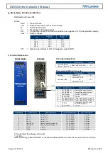
2. Terminal Explanation
FRONT PANEL
TOP SIDE
TOP SIDE CONNECTOR
Part Number
Vendor
Top Side Signal
Header Connector
S8B-PHDSS(LF)(SN)
JST
Recommended Mating Connector
Part Number
Vendor
Housing
PHDR-8VS
JST
Termninal Pins
SPHD-002T-P0.5
JST
or
SPHD-001T-P0.5
TERMINAL
FUNCTION
DESCRIPTION
RECOMMENDED †
MAX TORQUE *
1
Vo2 (-)
Output 2 (-)
10 – 16 AWG
0.5 Nm
2
Vo2 (+)
Output 2 (+)
10 – 16 AWG
0.5 Nm
3
Vo1 (-)
Output 1 (-)
10 – 16 AWG
0.5 Nm
4
Vo1 (+)
Output 1 (+)
10 – 16 AWG
0.5 Nm
5
On/Off Vo2
Remote On/Off (Output 2)
10 – 24 AWG
0.5 Nm
6
On/Off Vo1
Remote On/Off (Output 1)
10 – 24 AWG
0.5 Nm
7
VIN (-)
Input (-)
10 – 16 AWG
0.5 Nm
8
VIN (+)
Input (+)
10 – 16 AWG
0.5 Nm
† Ensure rated for voltage and current
* 4.4 lbf.in
Note: According to EN/UL60950-1 multi-strand flexible cables connected to the input require a ferrule.
PIN #1
PIN #2
PIN
FUNCTION
DESCRIPTION
1
Vo1 SENSE (+)
Remote Sense for Output 1
2
Vo2 SENSE (+)
Remote Sense for Output 2
3
Sync Signal
DO NOT CONNECT
4
Signal GND
Ground
5
Vo1 PWR GOOD Power Good Signal, Output 1
6
Vo2 PWR GOOD Power Good Signal, Output 2
7
CC Ref
Constant Current
(Consult
Technical Support)
8
Signal GND
Ground