INSTRUCTION MANUAL
CUS60M Series
TDK-Lambda
<Page>
Instructions for using the power supply in customer’s system
1. If the output of power supply is connected to FG in the application, the withstand voltage test between input and output
(FG) should be tested at 2kVAC.
2. If there is external noise filter and Y-caps connected at the input and output of the power supply, the voltage
distribution between primary and secondary circuit will be changed during the withstand voltage test, and may cause
test fail. In this case, please contact TDK-Lambda for the technical support and instructions.
7.
Mounting
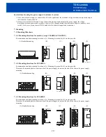
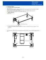
7-1. Mounting Directions
7-1-1. Mounting directions for models (except CUS60M/A,CUS60M/U)
Recommended standard mounting direction is (A). Mounting direction (B)-(E) are also possible.
(A) Standard mounting
(B)
(C)
(D)
(E)
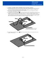
7-1-2. Mounting directions for CUS60M/A
Recommended standard mounting direction is (A). Mounting direction (B)-(E) are also possible.
Please use the mounting holes on bottom side of the power supply, do not use the side of the chassis for power supply
mounting.
(A) Standard mounting
(B) (C)
(D)
(E)
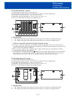
7-1-3. Mounting directions for CUS60M/U
Recommended standard mounting direction is (A). Mounting direction (B)-(E) are also possible.
Please use the mounting holes on bottom side of the power supply, do not use the side of the chassis for power supply
mounting.
(A) Standard mounting
(B)
(C)
(D)
(E)
9/19
CN1(INPUT)
CN1(INPUT)
CN1(INPUT)
CN1(INPUT)
INPUT
INPUT
CN1(INPUT)
CN1(INPUT)
INPUT
CN1(INPUT)
INPUT


