CME
・
All specifications are subject to change without notice.
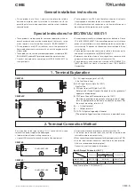
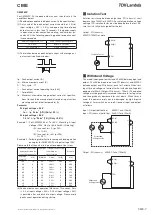
FG should be connected to the earth terminal of the apparatus.
If not, the conducted noise and output noise will increase.
Wire
FG
Metal spacer
Chassis (Conductor)
• The output load line and input line shall be separated and
twisted to improve noise sen-sitivity.
• Use all lines as thick and short as possible to make lower
impedance.
• Noise can be eliminated by attaching a capacitor to the load
terminals.
• For safety and EMI considerations, connect FG to ground
terminal of equipment where power supply is mounted on.
• Recommended screw torque is 0.49N
・
m (5kgf
・
cm).
• Select the wire materials to adapt the connector as follows.
INPUT : AWG#22-#18
OUTPUT : AWG#22-#18
5. Wiring Method
Refer to the following fuse rating and use high-braking capac-
ity fuse when selecting the external fuses that are to be used
on input line. Surge current flows when line turns on. There-
fore use slow-blow fuse or time-lug fuse. Do not use fast-blow
fuse. Fuse rating is specified by in-rush current value at line
turn-on. Do not select the fuse according to input current (rms.)
values under the actual load condition.
CME150 : 5.0A
CME240P : 6.3A
6. External Fuse Rating
Before concluding that this product is at fault, make the follow-
ing checks.
• Check if the rated input voltage is connected.
• Check if the wiring of input and output is correct.
• Check if the wire material is not too thin.
• Check if the output voltage control (V.ADJ) is properly ad-
justed.
• Check if the output current and output wattage is not over
specification.
• Audible noise can be heard during
dynamic-load
operation.
• Audible noise can be heard when input voltage waveform is
not sinusoidal wave.
7. Before concluding that the unit is at fault
CME-1003E
CME-9


