background image

42

43

2800 Laura Lane • Middleton, WI 53562  

|

  800.288.9383  

|

  www.tcsbasys.com  

Building Automation Systems

42

43

Appendices

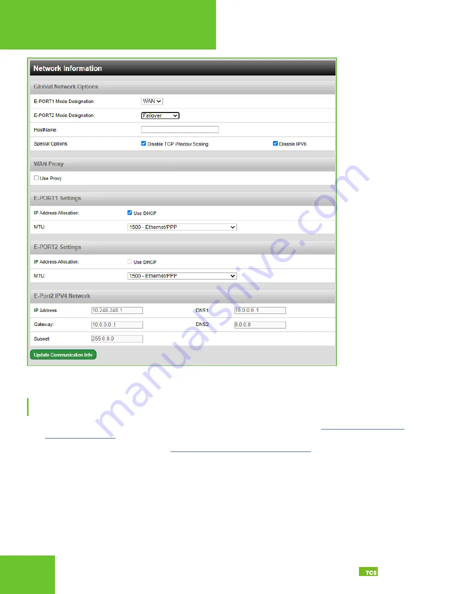
Global network options

Fail-Over Port Configuration Via CLI

NOTE: 

Configuring the Gateway in this manner requires a working knowledge of text-based user interfaces. Do not 

attempt this method of configuration if you are unfamiliar with text-based user interfaces.
1. 

Connect a keyboard and monitor directly to the QWL4.1 and reboot the device (See 

Appendix C: Monitor and 

Keyboard on page 26

).

2. 

Establish a connection to the CLI (see


Gateway Configuration via CLI on page 15

).

3.  Skip past the setup questions until you see the Failover settings. 
4.  Enable Failover by entering a “1”.

5.  In the Host Name field, enter the host name provided by your IT department.

6. 

Skip to the Local Ethernet 2 fields. Enter the failover network information provided by your IT department.

7.  Exit the CLI to save settings. Disconnect the monitor and keyboard. Do not reboot the QWL4.1.

Changes made via the CLI will take about five minutes to execute.

Содержание QWL4.1

Страница 1: ...2800 Laura Lane Middleton WI 53562 800 288 9383 www tcsbasys com 202311 Building Automation Systems Building Automation Systems Installation Manual QWL4 1 Integrated Building Manager Panel ...

Страница 2: ...net 14 No Communication with RS 485 Ports COM 1 and 2 Ubiquity Time out or No Data 14 Gateway Configuration 16 Introduction to Gateway Configuration 16 Gateway Configuration Via Laptop 16 Gateway Configuration via CLI 21 Lighting Pulse Meter Programming 24 Introduction to Lighting Pulse Meter Programming 24 Pulse Meter Module Programming 27 Meter Types 27 Appendices 29 Appendix A Local Management ...

Страница 3: ... unit Gateway Configuration Most units come with the Building Manager s Gateway preconfigured if your unit s Building Manager was preconfigured by TCS you can skip this section However some customers order their units without being configured beforehand for those customers we include this section which contains essential information necessary to set up the Building Manager Gateway Lighting Pulse M...

Страница 4: ...ent being controlled by the relay EEMS Enterprise Energy Management System A system of computer aided tools used by operators of electric utility grids to monitor control and optimize the performance of the generation or transmission system Firewall A technological barrier designed to prevent unauthorized or unwanted communications between computer networks or hosts Gateway The node in a computer ...

Страница 5: ...pplication programs can exchange data TCP IP Transmission Control Protocol Internet Protocol A set of standardized rules that allow computers to communicate on a network such as the internet UI User Interface The space where interactions between humans and computers occur e g keyboard mouse monitor USB Universal Serial Bus A standardized plug and play interface that allows a computer to communicat...

Страница 6: ... The QWL 4 0 comes with a one inch wiring access port pre drilled in the top of the unit Drilling into the unit to add additional wiring access ports is at your own risk Use caution when drilling into the unit be sure to capture all metal shavings The unit MUST be powered down while drilling into the unit Factory IP Network Address Configuration The QWL4 1 is typically purchased pre configured to ...

Страница 7: ...estart the unit Exterior views Cloud Connectivity Ethernet Port Connect an Ethernet cable to the Ethernet port on the side of the QWL4 1 Connect the other end of the cable to your network switch port as determined by your local network administrator or IT department NOTE If using a cellular modem provided by TCS connect the Ethernet cable to the LAN port on the modem contact TCS Technical Support ...

Страница 8: ... the inputs on Com Port panel or on the Serial Board adjacent to the Gateway see RS 485 Controller Network Wiring Setup on page 10 USB Ports 1 4 As an option you can connect up to 64 RS 485 controller networks via the four USB ports on the side of the Ubiquity Cloud Gateway by using QD1010 USB to RS 485 converters not included USB CABLE USB CABLE ETHERNET CABLE Not Used Not Used USB PORT 2 USB POR...

Страница 9: ...ng components Ubiquity Cloud Gatewayr SLQ218 Lighting Controller SLQ100 Electrical Pulse Meter These components accept the following inputs SLQ218 Lighting Controller Eight dry contact digital inputs Two 0 5VDC analog inputs Closeup of lighting controller inputs SLQ100 Electrical Pulse Meter Four pulse meter inputs Closeup of pulse meter inputs DIGITAL INPUTS ANALOG INPUTS Pulse Meter Inputs Z1 K ...

Страница 10: ...h the network On controllers with displays this can be done from the controller using its keypad and display by using TCS Insight software or by calling TCS Technical Support 800 288 9383 ext 2 TCS Technical Support can access the QWL4 1 online and change the address of a controller Network Wiring The QWL4 1 has a serial board with two RS 485 ports that will accept Modbus and TCSbus Connections Th...

Страница 11: ...contact TCS Technical Support 800 288 9383 ext 2 Three Wire Network Wiring Follow this wiring diagram for all three wire systems this is common NOTES In the middle of the network all network wiring shields should be twisted together and taped off to prevent accidental grounding More than one ground on the network wiring can result in communication failure A maximum of two terminating resistors can...

Страница 12: ... lers use the second RS 485 port or additional QD1010 adapters 2 Each controller must use the same baud rate and be assigned a unique address Two Wire Network Wiring Follow this wiring diagram for two wire Modbus wiring systems this is not common Two wire diagram A B Shield A B A B Earth Ground Only at one end Drain Wire Last in Daisy Chain 120Ω Terminating Resistor COM 1 REF A B Drain Wire 120Ω T...

Страница 13: ... cell modem if utilized 4 Connect the power source to the QWL4 1 and apply power If your QWL4 1 was preconfigured by the TCS factory or another user it will automatically go online and contact Ubiquity Cloud 5 You MUST call TCS Technical Support 800 288 9383 ext 2 to verify connection and activate the unit 6 If your QWL4 1 s Panel Gateway was not ordered preconfigured You can configure it at this ...

Страница 14: ...ollow polarity Make sure the A wire goes to the A terminal in all devices as well as the wires that go to B and REF terminals No LAN Link to the Internet Verify the network cable is connected correctly and make sure the LEDs next to the Ethernet jack are properly illuminated For example a solid green LED at the RJ 45 LAN connector usually indicates that the QWL4 1 is either connected or receiving ...

Страница 15: ...ating the serial ports are operational is located inside the enclosure on the Ubiquity Cloud board If none of these lights are functioning Ubiquity Cloud is not coming online This could be because the network communication is not set properly or there is a bad firewall proxy setting There also could be a bad connection a bad cable a bad ground or a bad component Contact TCS Technical Support 800 2...

Страница 16: ...lt Gateway login and password which is supplied to customers upon request It is the customer s responsibility to configure a custom login and password Contact TCS Technical Support 800 288 9383 ext 2 for information on managing Gateway login credentials Gateway Configuration Via Laptop Once you have made a connection and have logged in see Appendix A Local Management Port on page 29 you can config...

Страница 17: ...t select a Network Polling Cycle Time for the QWL4 1 This is the time interval that the unit will poll the entire network of controllers on all ports You must select whether to allow caching the host name via DNS Typically this is left unchecked You must select how often the QWL4 1 connects to the Ubiquity Cloud Server Typically this is set to Always On Network Polling Cycle Time Default 1 minute ...

Страница 18: ... Select the communications protocol being used on each port TCSbus is selected by default Baud Rate This is the data transmission speed on the network The Baud Rate must be the same selection for the port configuration as it is on every device communicating to that port Time out Period This is the number of milliseconds the port on the QWL4 1 will wait for a response from the network devices befor...

Страница 19: ...ally assigned when communication is established MTU Adjustments Adjusting the MTU down may allow gateways to communicate with smaller TCP packet sizes This may be useful if you are using cell modems not capable of passing a TCP packet with a size of 1500 Proxy If a proxy is required select Static Proxy from the drop down menu and enter all the related details in the fields that appear When you are...

Страница 20: ...mation Commissioning Tools You can access a separate page containing various commissioning tools by clicking the Commissioning Tools button at the bottom of the Security Information page These tools provide you with access to managing the communication status of the QWL4 1 and the controller network connected to it Commissioning tools ...

Страница 21: ... the right side of the Controller View title bar will refresh each controller s status System Commands This section describes how to set up system flags for the QWL4 1 Reboot Unit sets a flag which will shut off and restart the QWL4 1 within a five minute cycle Check for Update contacts the Ubiquity Cloud Server for any updates relevant to its particular model number and software version Once the ...

Страница 22: ...22 2800 Laura Lane Middleton WI 53562 800 288 9383 www tcsbasys com Building Automation Systems 22 Gateway Configuration Command Line Interface Screens Gateway configuration Application options ...

Страница 23: ...23 2800 Laura Lane Middleton WI 53562 800 288 9383 www tcsbasys com Building Automation Systems 23 Gateway Configuration Proxy options Extended application options ...

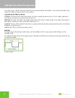
Страница 24: ...mpted to change your login credentials Ubiquity Cloud login screen Lighting Module Programming Channel Event Scheduling The lighting module is equipped with eight independent event channels each with their own schedule The schedules are configured using military time For example If the occupied or ON time for a particular day is from 8 00 AM to 5 00 PM enter 8 00 to 17 00 From the Schedule window ...

Страница 25: ...ND To use this input with a threshold and hysteresis Channel Power section to shut off lighting channels select the relevant lighting channels Enable AI2 Threshold checkboxes and enter a threshold and a hysteresis to be used If AI1 is not used the channel power threshold MUST equal the scaling high limit Select whether to allow the time clock output Digital Output Mode to be Normally Open or Norma...

Страница 26: ...al Time NOTE For non North American Daylight Saving Time set the manual DLS Day Light Saving Time Channel Occupant Override A good example of the use of this feature is to allow for a cleaning crew to come in guaranteeing the lights would not remain on after the crew has left This is the number of minutes from 0 to 255 4 hr 15 min which the controller will bring a system that is OFF to ON when its...

Страница 27: ...d demand for that particular meter For each of the four SEQ100 meter inputs there are five selectable options 1 ELEC 1 PH Electric single phase meter 2 ELEC 3 PH Electric three phase meter 3 GAS Gas meter 4 WATER Water meter 5 BTU BTU meter Utility pulse meters can be one of two different types depending on whether they count the leading and trailing edges of the pulse or only the leading edge of ...

Страница 28: ... and is set to 1 PPR Value The value of the PPR is the number of pulses per 1 kWh 1 BTU 1 gallon minute For example one pulse per 1 kWh equals 10 pulses per 1 kWh so the PPR value is set to 10 Constant The value of the constant for the meter is usually provided by the utility company and many times is located on the electric or gas bill Set to 1 CU FT P The value for Cubic Feet per pulse Set to 1 ...

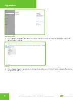
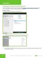
Страница 29: ...rface Card NIC 2 Ethernet cable Connection Setup Ethernet Cable Connect one end of the Ethernet cable to the Local Management Ethernet Port on the QWL4 1 see Power and Communication Connections on page 7 and the other end to the laptop s Ethernet port Laptop The steps below require changing the network settings of the laptop this is done at your own risk Windows 10 or Later 1 Search for Ethernet S...

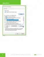
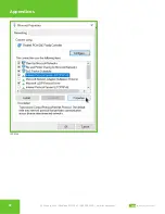
Страница 30: ...hange adapter options 3 On the Network Connections panel locate the Ethernet interface that is connected to the cable Right click on the item and select Properties Properties 4 On the Ethernet Properties panel locate the Internet Protocol Version 4 TCP IPv4 Select that option then click on the Properties button ...

Страница 31: ...31 2800 Laura Lane Middleton WI 53562 800 288 9383 www tcsbasys com Building Automation Systems 31 Appendices TCP IPv4 ...

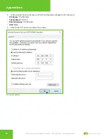
Страница 32: ...ding Automation Systems 32 Appendices 5 On the Internet Protocol Version 4 TCP IPv4 Properties change the IP schema to IP Address 10 248 248 2 Subnet Mask 255 0 0 0 Default Gateway 10 248 248 2 DNS Blank 6 Click on the OK button and close the window Port to static settings ...

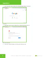
Страница 33: ... Systems 33 Appendices 7 Launch any web browser and type in the following address https 10 248 248 1 Device address 8 Depending on your browser s configuration you may get the following screen Privacy error warning screen 9 Click on the Advanced button in the Privacy Error Warning screen ...

Страница 34: ...sys com Building Automation Systems 34 Appendices 10 Click on the Proceed link to take you to the next screen Proceed screen 11 Enter the Login user name and password Login screen 12 Configure the Gateway as needed See Gateway Configuration Via Laptop on page 16 ...

Страница 35: ...gement Port on page 29 and wish to revert back to its previous configuration follow the steps below Windows 10 or Later 1 Search for Ethernet Settings and click the Open link Ethernet settings 2 On the Ethernet Settings panel and click the Change adapter options link Change adapter options 3 On the Network Connections panel locate the Ethernet interface that is connected to the cable Right click o...

Страница 36: ... WI 53562 800 288 9383 www tcsbasys com Building Automation Systems 36 Appendices Properties 4 On the Ethernet Properties panel locate the Internet Protocol Version 4 TCP IPv4 Select that option then click on the Properties button ...

Страница 37: ...37 2800 Laura Lane Middleton WI 53562 800 288 9383 www tcsbasys com Building Automation Systems 37 Appendices TCP IPv4 ...

Страница 38: ...Automation Systems 38 Appendices 5 On the Internet Protocol Version 4 TCP IPv4 Properties General tab 6 Click on the Obtain an IP address automatically radio button 7 Click on the Obtain DNS server automatically radio button 8 Click on the OK button Revert back to DHCP settings ...

Страница 39: ...ect the cable to the monitor and to the QWL4 1 matching up the corresponding ends HDMI DP See Power and Communication Connections on page 7 Power on the monitor and switch to the proper input based on the cable used 2 Plug the USB cable into a free USB port on the QWL4 1 Test keyboard connectivity by pressing Caps Lock to see if the LED on the keyboard illuminates 3 Reboot the unit by pressing and...

Страница 40: ... Line Interface CLI by connecting a keyboard and monitor to the device See Appendix C Monitor and Keyboard on page 26 Hardware Internet Requirements You must provide a secondary Internet connection that is separate from the primary connection Central Server Location This failover server connection can be connected to a wired internet connection or it can utilize a cellular modem Fail Over Port Con...

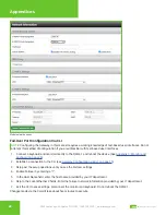
Страница 41: ...ommends contacting your IT department before making any changes to the default settings Click on the green Update Application Info button beneath the RS485 Network Port Configuration section to save the failover server location and other settings Global Network Options Section Click on the E PORT2 Mode Designation drop down menu and select Failover In the Hostname field enter the failover network ...

Страница 42: ...tly to the QWL4 1 and reboot the device See Appendix C Monitor and Keyboard on page 26 2 Establish a connection to the CLI see Gateway Configuration via CLI on page 15 3 Skip past the setup questions until you see the Failover settings 4 Enable Failover by entering a 1 5 In the Host Name field enter the host name provided by your IT department 6 Skip to the Local Ethernet 2 fields Enter the failov...

Страница 43: ...43 2800 Laura Lane Middleton WI 53562 800 288 9383 www tcsbasys com Building Automation Systems 43 Appendices Failover URL Settings E port 2 mode settings ...

Страница 44: ...ght software you will need Laptop PC running Windows 95 or later with an available USB port USB A to B Cable RS 485 Cable QD1010 USB Converter wired networks OR QW1010a Converter wireless networks Setup 1 Inside the QWL panel disconnect the internal USB cable leading to the Panel Gateway This will isolate the SLQ218 and pulse meter for polling USB cable to disconnect 2 Connect an RS 485 cable from...

Страница 45: ...he Insight software and select Install FTDI Driver Follow the installation instructions 5 Select the new COM port and click on the Open Port button 6 Click on the second Poll tab This will cause the software to recognize the SLQ218 and SEQ100 Second poll tab 7 Click on the SLQ218 icon to access the programming tabs See Lighting Pulse Meter Programming on page 24 8 After programming the SLQ218 clic...

Отзывы: