HR150, 200; ER150, 200 FRESH AIR VENTILATION SYSTEMS
9
68-0269
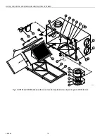
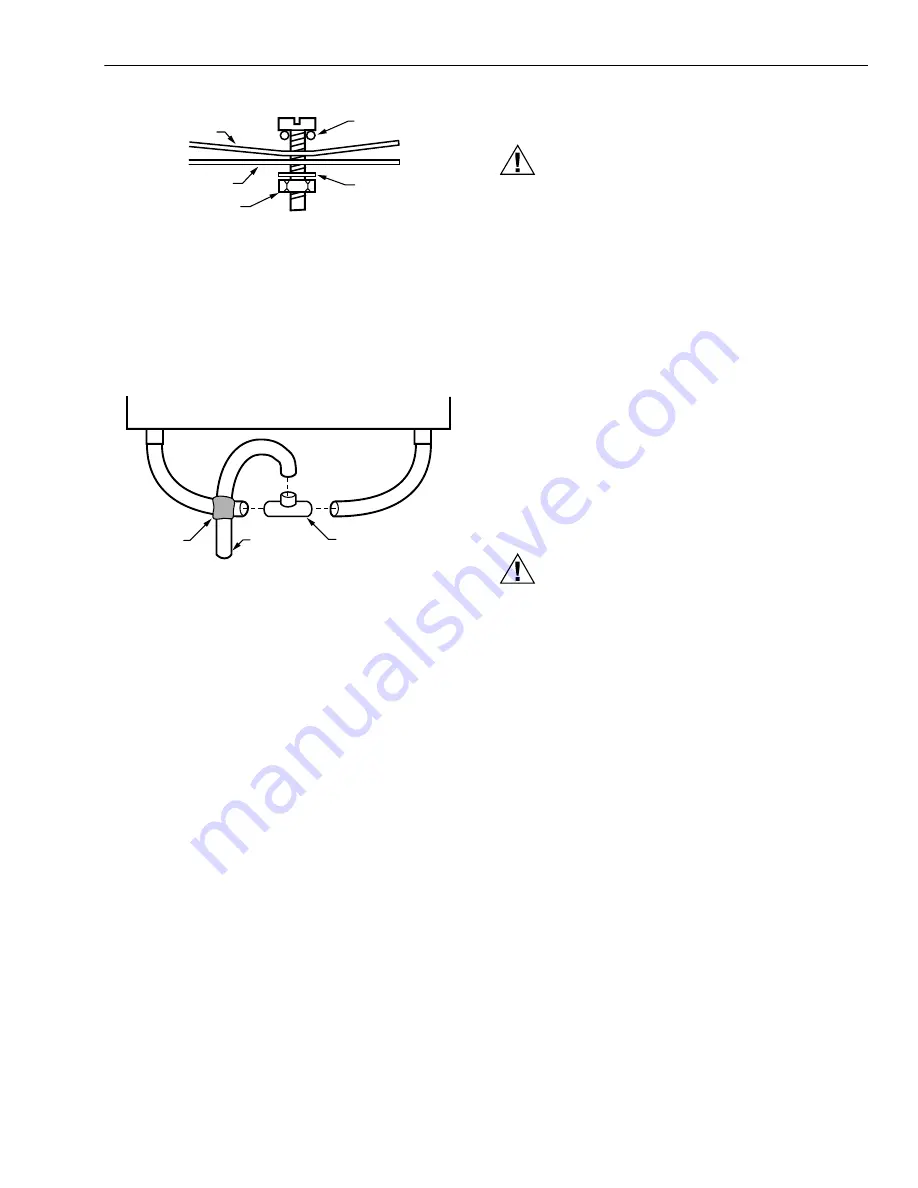
Fig. 8. Installing drain line.
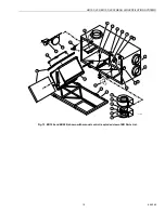
Construct a P-trap using the plastic T-fitting provided.
1.
Cut two lengths of 1/2 in. ID hose and connect each
drain fitting to the end of the T-fitting.
2.
Position the center leg of the T-fitting so it points
upward.
3.
Connect the drain line to the center leg and tape it in
place to prevent any kinks. See Fig. 10.
Fig. 9. Installing P-trap.
This creates a trap that will hold some condensation and
prevent odors from being drawn up through the drain hose
into the unit. If the unit is installed during a season when it is
unlikely that condensation will form, fill the trap with tap water.
WIRING
CAUTION
Electrical Shock Hazard.
Can cause personal injury.
Be sure the ventilator is properly grounded. To prevent
electric shock when cleaning or servicing the unit,
confirm the polarity of the power line that is switched
by the safety (disconnect) switch.
The hot line (black) is the proper line to be switched. See
Fig. 11. To confirm the proper polarity, use a voltmeter or test
lamp to make sure there is no power after the switch when the
door is open. Check between that point and ground (on the
cabinet). This process must be done because occasionally
some dwellings are improperly wired.
Heat Recovery Ventilator (HRV) and Energy
Recovery Ventilator (ERV) Connections
The connector is a 3-prong, 120 Vac plug with ground. If
further wiring is required, Honeywell recommends that a
licensed electrician make all electrical connections. It is very
important that the unit be properly grounded.
Digital Fan Timer Connections
CAUTION
Electrical Hazard.
Can cause equipment damage.
Disconnect HRV/ERV from power source before
connecting or disconnecting digital fan timer or other
device to HRV/ERV high-speed override terminals.
IMPORTANT
Do not connect external power sources to the high
speed override terminals.
Mount the digital fan timer in a full or one-half depth electrical
box in the living space. See Fig. 11 for the 20 minute timer and
the 20/40/60 minute timer wiring diagrams. (See accessory
parts list, items 9 through 11, for digital fan timer selection.)
M6552
DRAIN
PAN
O RING
HR
BOTTOM
WASHER
NUT
TO DRAIN
T FITTING
TAPE
M6551


