background image

6

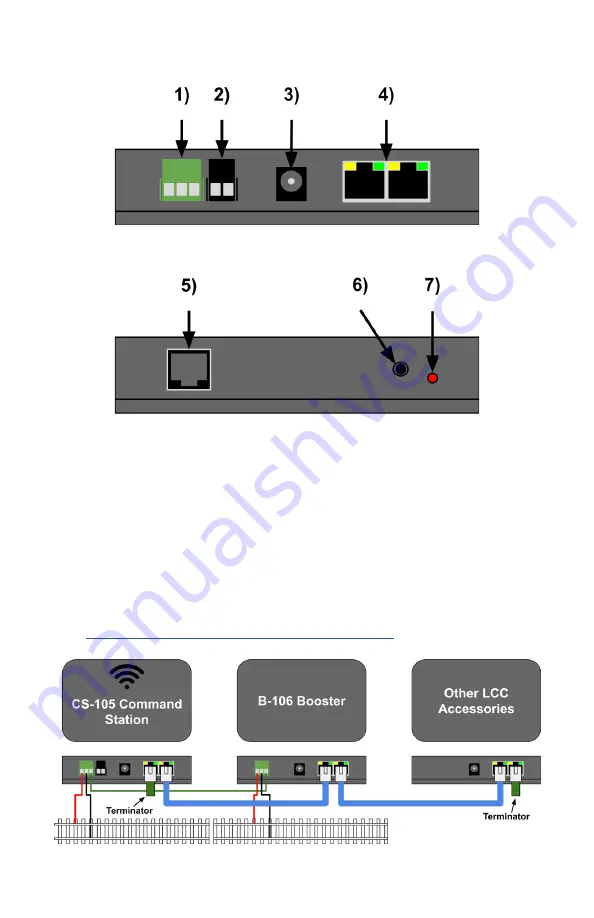
CS-105 Side A

CS-105 Side B

Connecting TCS Boosters and LCC Devices

The CS-105 features a NMRA S-9.1.2 Full Scale Interface with a 

maximum output current capacity of 400mA.
To connect LCC CAN devices, use Cat 5 or better cables, and daisy 

chain the devices in linear fashion. Insert an LCC terminator at each end 

into the leftover socket (two are provided with the CS-105).
TCS DCC Boosters should be connected as shown in the diagram below. 

To connect Boosters from other manufacturers, a Booster Adapter board 

is available from TCS. 
Visit 

https://docs.tcsdcc.com/wiki/Booster_Interface

 for more info.

Содержание CS-105

Страница 1: ...CS 105...

Страница 2: ...ices 6 Diagnostic LED Overview 7 Connecting to an Existing WiFi Network 8 WiFi Access Point Configuration 8 WiFi Configuration Window 9 Computer Interface 10 Operations 12 Locomotive Operations 12 Loc...

Страница 3: ...p to 10 LCC WiFi throttles via external WiFi Access Point Router Up to 250 LCC throttles wired or via auxiliary LCC WiFi base stations Up to 62 Cab Bus NCE wired and wireless Ramtraxx and Syste mOne t...

Страница 4: ...ection with the on screen message Connected to LAYOUTWIFI and the text LCC will be vis ible on the top right under the signal strength indicator 3 Place a locomotive on the track press the Locomotive...

Страница 5: ...nnectors support LCC CAN bus Up to 400 mA of power is provided to each socket The DCC signal is available for auxiliary Boosters on pins 4 and 5 The jacks contain four LEDs left to right Track Status...

Страница 6: ...ices use Cat 5 or better cables and daisy chain the devices in linear fashion Insert an LCC terminator at each end into the leftover socket two are provided with the CS 105 TCS DCC Boosters should be...

Страница 7: ...to an external WiFi Access Point ON ON WiFi connected to an external Access Point or Router ON OFF WiFi Access Point mode ON ON WiFi Full The limit of how many WiFI devices throttles can be connected...

Страница 8: ...mple of what the webpage will look like 5 In the WiFi Mode setting select WiFi Client then press Apply 6 Scroll down to Add WiFi Click Select Network then select your WiFi net work or enter it to the...

Страница 9: ...9 WiFi Configuration Window...

Страница 10: ...e built in wireless computer interface For this method you will not need any additional hardware but your computer will take up one of the available wireless throttle slots Connect your computer to th...

Страница 11: ...on The TCS throttle screen will show you an IP address which could look something like this Use this information to help you configure the JMRI settings like in this example below 11 NOTE the IP addre...

Страница 12: ...for DCC decoders or between protocol version I and II for M rklin Motorolla decoders Note Throttles will always display 128 speed steps independently of the speed step mode used for the track Functio...

Страница 13: ...highlight the bit decomposition of the current value Use buttons 0 to 7 to turn on and off the indi vidual bits The throttle will automatically add up the individual numbers C Finally press the key to...

Страница 14: ...he dialog or press in the bottom field More Update Complete Select Menu Settings DCC System Settings to access the CS 105 s Settings on a TCS throttle To see the help text for any menu item highlight...

Страница 15: ...thority to operate the equipment FCC 15 105 This equipment has been tested and found to comply with the limits for a Class B digital device pursuant to part 15 of the FCC Rules These limits are design...

Страница 16: ...For more information about your CS 105 device please visit our website www tcsdcc com CS 105 QSG Revised July 2022 TCS Command System...

Отзывы: