background image

 Air Conditioner Service Manual 


33


Resistance at 2

5℃: 

kΩ.


TH1: indoor room temperature sensor and outside air temperature sensor


TH2: indoor exchange temperature sensor and outside exchange temperature sensor   

Before measuring resistance, disconnect connectors as shown above. 


Содержание TFC-24HRA

Страница 1: ...0180321 Models TFC 24HRA TOC 24HNA TFC 48HRA TOC 48HSA CONTENTS 1 IMPORTANT NOTICE 2 PRODUCT DIMENSIONS 3 REFRIGERATION CYCLE DIAGRAM 4 OPERATION DETAILS 5 WIRING DIAGRAM 6 EXPLOSION VIEW AND PART LISTS 7 PRECAUTION 8 NAMES OF PARTS 9 INSTALLATION 10 TROUBLE SHOOTING ...

Страница 2: ... for the interpretation of this information nor can it assume any liability in connection with its use The information specifications and parameters are subject to change due to technical modification or improvement without any prior notice The accurate specifications are presented on the nameplate label How to order spare parts To have your order filled promptly and correctly please furnish the f...

Страница 3: ...3 2 PRODUCT DIMENSIONS Indoor Unit Outdoor Unit Model Indoor unit Outdoor unit A B C D E F G H I J K TFC 24HRA 480 330 1740 900 650 307 623 399 349 65 63 TFC 48HRA 540 420 1780 940 1250 340 600 400 375 50 63 Indoor unit Outdoor unit TFC ...

Страница 4: ...ry Compressor Accumulator Heat exchange condenser Heat exchange Evaporator 2 way valve Liquid side 3 way valve Gas side Cooling Heating Gas side 3 way valve Liquid side 2 way valve Heat exchange Evaporator Heat exchange condenser Accumulator Compressor 4 way valve Capillary Assembly Check valve ...

Страница 5: ...Only then you CAN NOT preset the Heating operation with the remote controller 9 9 1 2 4 3 5 6 10 7 MODE button ECO button FAN SPEED button TEMP UP button TIMER button SLEEP button TEMP DOWN button To select the mode of operation In cooling mode press this button the temperature will increase 2 on the base of setting temperature In heating mode press this button the temperature will decrease 2 on t...

Страница 6: ...able to retain and restore the original mode when being turned on or the power supply is resumed if the auto restart function activated power off after power on while if the auto restart function isn t activated the A C enters standby state Heat pump Mode Initial RT Initial ST Cooling RT 26 C 23 C Dry 26 C RT 20 C 7 C Heating RT 20 C 23 C Cooling only Mode Initial RT Initial ST Cooling RT 26 C 23 ...

Страница 7: ... ST CRT 1 C the compressor is running b When ST CRT 1 C the compressor stops c When 1 C ST CRT 1 C the compressor keeps its original state 2 Outdoor fan motor and the compressor run simultaneously except for defrosting 3 The control of indoor fan motor a Indoor fan motor can operate by automatic low middle or high airflow speed circularly b Indoor fan motor automatic airflow speed control it works...

Страница 8: ... Off Tim be in accord ing during d ing optiona m run into de 3 d c all require ax ᇞIPT 0min the co tion 1 the fir me should b is more than erature is le e set is 8 mi or is operatin on wind tem mpressor ope sting accordi Conditioner Se nomic opera ediately but ing Sleep F dance with o efrosting no l function st frosting onc ed to meet ompressor ru rst running ti be determine Figure 3 n or equal to...

Страница 9: ...he machine runs into defrosting and last for 8 min if the accumulative totally less than 30min but accord with one of the condition option 1 3 then the machine runs into defrosting at the option 1 3 and the accumulative total time restarts from 0 Conditions for quitting defrosting 1 The quitting conditions for option 1 option 2 and 4 the machine quits from defrosting if any one below condition met...

Страница 10: ...r then no changed anymore 3 The machine will automatically shut up after running 10 hours under sleep mode When Timer ON and Sleep mode are implemented at the same time the Sleep mode can not be functioned 7 Timer function The timer can preset between 10min to 24h when the time set less than 10 hours the displayed time shown by 0 5 hour as the unit when the time set more than or equal to 10 hours ...

Страница 11: ...ection the compressor can t start up until it stops 3 min later except for the defrosting process c After the compressor started it s operation state remains the same within 3 min even when ST RT variation 2 Anti frosting protection of indoor evaporator Cooling mode If IPT 0 C detected in consecutive 3 min compressor and outdoor fan motor to be stopped operation indoor fan motor runs at high speed...

Страница 12: ...re Once cycle E1 IPT Sensor Failure Twice cycle E2 Outdoor unit protected 5 times cycle E5 While failure happens the code displayed statically if there are several failure codes reported at the same time then failure codes appears by turns every eight seconds correspondingly 6a Sensor s failure protection when the sensor tested temperature out of the range 50 C T 110 C sensor failure is determined...

Страница 13: ...Air Conditioner Service Manual 12 5 WIRING DIAGRAM MODEL TFC 24HRA TOC 24HNA INDOOR UNIT OUTDOOR UNIT ...

Страница 14: ...Air Conditioner Service Manual 13 MODEL TFC 48HRA TOC 48HSA INDOOR UNIT FM OUTDOOR UNIT ...

Страница 15: ...nditioner Service Manual 14 6 EXPLOSION VIEW AND PARTS EXPLOSION VIEW Mode TFC 24HRA TFC 48HRA INDOOR UNIT 12 25 28 26 27 29 30 23 24 22 21 20 19 17 18 16 15 14 13 37 32 31 33 34 35 36 1 11 10 8 9 3 2 4 7 5 6 ...

Страница 16: ...2 Heat insulation board Cover 1 18 1090520136 Display PCB 1 19 1070710421 Display PCB Supporter 1 20 1070710014 Display PCB Cover 1 21 1070710424 Spring 1 22 1070710423 Button 1 23 1020710001 Ornamental Board 1 24 1070710414 Down panel 1 25 1070710010 Fastener 1 26 1070520147 Air Filter 1 27 1170230009 Indoor Sensor 1 28 1074060115 Lead Flow Circle 1 29 1080520218 Inside Electrical Box Cover 1 30 ...

Страница 17: ...1 17 1090520136 Display PCB 1 18 1070710422 Display PCB Supporter 1 19 1070710014 Display PCB Cover 1 20 1070710424 Spring 1 21 1070710423 Button 1 22 1020710001 Ornamental Board 1 23 1071200021 Down panel 1 24 1070710016 Fastener 1 25 1070300003 Air Filter 1 26 1170230009 Indoor Sensor 1 27 1074090102 Lead Flow Circle 1 28 1084090113 Inside Electrical Box Cover 1 29 1070010004AA Centrifugal Fan 1...

Страница 18: ...Air Conditioner Service Manual 17 MODEL TAC 24CHFA C OUTDOOR UNIT 10 11 8 9 6 7 5 4 20 14 12 13 15 16 17 18 19 3 2 21 22 24 23 25 26 1 ...

Страница 19: ...0017 4 way Valve 1 12 1120700344 4 way Valve Assembly 1 13 1081990178 Base 1 14 1081990039 Right Plate 1 15 1120120024 Two way Valve 1 16 1081990041 Valve Supporter 1 17 1120130037 Three way Valve 1 18 1070350971 Electrical Box Cover 1 19 1074060118 Cable Clamp 1 20 1170200053 Terminal 1 21 1170100030A Fan Motor Capacitor 1 22 1170100007B Compressor Capacitor 1 23 1080010006 Capacitor Strip 1 24 1...

Страница 20: ...Air Conditioner Service Manual 19 OUTDOOR UNIT Mode TOC 48HSA ...

Страница 21: ...utdoor fan capacitor 2 3160080001 AC contactor 1 3171990066 Switch of low pressure 1 3171990210 Switch of high pressure 1 3172522102 Discharge temp sensor 1 3092520401AB Outdoor PCB 1 11 1070350971 Handle 1 12 3210027077 Right back clapboard 1 13 3120120053 Three way Valve 1 14 3210010257 Two way Valve 1 15 3080028197 Partition plate 1 16 3120110018 4 way valve 1 3172510101 Winding of 4 way valve ...

Страница 22: ... accordance with the wiring rules z The air conditioner must be installed by professional or qualified persons Do not install the appliance at a distance of less than 50 cm from inflammable substances alcohol etc Or from pressurized containers e g spray cans z If the appliance is used in areas without the possibility of ventilation precautions must be taken to prevent any leaks of refrigerant gas ...

Страница 23: ...ilures z The user is responsible for having the appliance installed by a qualified technician who must check that it is earthed in accordance with current legislation and insert a thermomagnetic circuit breaker z The batteries in remote controller must be recycled or disposed of properly Disposal of Scrap Batteries Please discard the batteries as sorted municipal waste at the accessible collection...

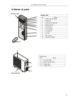
Страница 24: ...o Name 1 Airflow direction flaps 2 Deflectors 3 Indoor unit rating label 4 Signal receiver 5 LED Display 6 Control panel 7 Front panel 8 Air filter 9 Front panel 10 Remote controller Outdoor unit No Name 8 Air outlet grille 9 Electronic box cover 10 2 way valve 11 3 way valve 8 9 10 11 OUTDOOR UNIT ...

Страница 25: ...d be less than 20m Indoor unit Outdoor unit be less than 5m Height should Should be less than 20 m Mode Standard length m Refrigerant piping Max length m A Additional refrigerant Calculation g 20g m A 5m TFC 24HRA TOC 24HNA 5 0 20 30g m TFC 48HRA TOC 48HSA 5 0 20 40g m Connecting cables The power cord should be selected according to the following specifications sheet Appliance Amps Wire Size 5 AWG...

Страница 26: ...sary spaces as shown in the picture Select a place where the filter can be easily taken out OUTDOOR UNIT Do not install the outdoor unit near sources of heat steam or flammable gas Do not install the unit in too windy or dusty places Do not install the unit where people often pass Select a place where the air discharge and operating sound level will not disturb the neighbours Avoid installing the ...

Страница 27: ... screw terminals by following the numbering Use wire size suitable to the electric power input see name plate on the unit and according to all current national safety code requirements Note The cable connecting the outdoor and indoor units must be suitable for outdoor use An efficient earth connection must be ensured If the power cable is damaged it must be replaced by an authorized Service Centre...

Страница 28: ...tal for the success of the installation 1 Place the drain hose below the piping taking care not to create siphons 2 The drain hose must slant downwards to aid drainage 3 Do not bend the drain hose or leave it protruding or twisted and do not put the end of it in water If an extension is connected to the drain hose ensure that it is lagged when it passes into the indoor unit Insert the pipe connect...

Страница 29: ... humidity left inside the refrigerant circuit can cause compressor malfunction After having connected the indoor and outdoor units bleed the air and humidity from the refrigerant circuit by using a vacuum pump The air and humidity left inside the refrigerant circulation can cause compressor malfunction After having connected the indoor and outdoor units bleed the air and humidity from the refriger...

Страница 30: ...t does not operate at all Power supply voltage check Connector contact check Power trans output voltage PCB assembly check Power receptable voltage Product input voltage PCB assembly Power input voltage Driving load terminal Display PCB connector AC about 12 3V 29 ...

Страница 31: ...ature sensor open short check Thermistor and evaporator surface contact check Clearance is needed 5mm Connector check Contact power Connector check Contact power Disconnection short circuit check of connecting wire OLP High pressure switch Low pressure switch check Electric wire connection check for outdoor side Operation mode dehumidifying check Compressor motor detail check PCB assembly check Ch...

Страница 32: ...hort circuit mal connection Vane motor check PCB assembly check vane motor driving circuit Replace the vane motor Replace the PCB Heating operation ON by remote controller Connector check If the 4 way valve is ON tick sounds PCB assembly 4 way valve connection check outdoor unit connecting wire check Check the voltage of 4 way valve coil 4 way valve coil resistance check 31 ...

Страница 33: ...65 14 27 567 4 219 31 3 981 2 192 76 0 895 0 746 13 26 239 4 186 32 3 836 2 146 77 0 869 0 728 12 24 984 4 152 33 3 697 2 101 78 0 843 0 710 11 23 795 4 117 34 3 563 2 057 79 0 819 0 692 10 22 671 4 082 35 3 435 2 012 80 0 795 0 675 9 21 606 4 045 36 3 313 1 969 81 0 773 0 658 8 20 598 4 008 37 3 195 1 926 82 0 751 0 641 7 19 644 3 969 38 3 082 1 883 83 0 729 0 625 6 18 732 3 930 39 2 974 1 842 84...

Страница 34: ...Resistance at 25 5 kΩ TH1 indoor room temperature sensor and outside air temperature sensor TH2 indoor exchange temperature sensor and outside exchange temperature sensor Before measuring resistance disconnect connectors as shown above ...

Отзывы: