


4. ALIGNMENT PROCEDURE
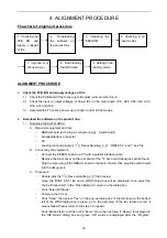
Flowchart of alignment procedure
ALIGNMENT PROCEDURE
1.
Check the PCB BD. and supply voltages of ICs:
1) Check the PCB board if there are any cold solder joints and short on it.
2) Check the input or output voltages of Power ICs on the main board: U18, U28, U29, U30, U32,
U33, U37 and U38.
3) Assemble the TV set and power up to check it under all the modes.
2.
Download the software on the product line:
1)
Download the S/W of UOC3:
A. Required equipment and tool;
DEBUG board (with a 6-pin connector plug), Switch board
Parallel
interface
connector
PC
Loading tool and program: “I
2
C_DeviceHandling_3_9”, “WISP2.5.5” and “*.hex” file
B. Connecting the equipment:
Connect the DEBUG board to a PC with a parallel interface cable.
Remove the tuner cover on the rear panel of the TV set, and a debug jack will be found.
Plug the 6-pin plug of the DEBUG board to the switch board, then plug the switch board
into the debug jack.
C. Procedure:
Double-click the “I
2
C_DeviceHandling_3_9” file to setup.
Open the “WISP 2.5.5” file and a WISP dialog box will be displayed, then select the
choice “Picasso N2” in the “Flash Memory” column on the dialog box.
Click “Enter ISP Mode”.
Power up the TV set.
Click “Send”, then select “Yes” on the pop-up dialog box. If the left lamp on the bottom
left of the WISP dialog box is green, go to the next step. If the two lamps are red, it
means failed. Please return to the step 3 to repeat.
Click “Erase Flash” and then click “Send”. Go to the next step if “Ready” is displayed in
the “ISP status” dialog box and green “OK” words are displayed after the “Program”,
1. Checking the
PCB BD. and
supply voltages
of ICs
2. Downloading
the software on
the product line
7. Setting in the
Factory mode
3. Initializing the
EEPROM
4. Checking in all
input modes
5. Adjustment of
White Balance
6. Downloading
the DDC data
18
Содержание LCD2326LV
Страница 39: ...39 ...