background image


Part # TCI-9006 

Revised 9/6/2016 

Toll Free: 1.888.776.9824 
www.tciauto.com 

TCI

®

 Automotive 

151 Industrial Dr. 

Ashland, MS  38603 

Phone:  662.224.8972 


Step 4 — Installation of TCI Wiring Harness: 

Most  applications  will  accept  the  OE  solenoid. 
All


two-wire  solenoids  are


acceptable.  If  you 

have a solenoid with only one wire, it 

cannot

 be 

used.  You  may  purchase  the  proper  solenoid 
from  GM,  part  number  8654126.  Using  your 
OEM,  two-wire  solenoid,  cut  both  wires 
allowing  about  2-1/2"  for  splicing  to  the  TCI

®


wiring harness. (

Note: 

Look closely at the black 

plastic  connector  on  the  new  TCI

®

  harness. 

Notice  that  each  terminal  position  is  labeled  A 
through  D.  This  instruction  will  refer  to  these 
positions  so  that  your  connections  are  made 
properly.) To connect your solenoid to the TCI

®


wiring  harness,  use  the  splice  connectors 
provided.  Connect  the  positive  solenoid  wire  to 

the  wire  going  to  Terminal  A  on  the  wiring 
harness, then connect the negative solenoid wire 
to the harness wire going to Terminal B.


Install  wiring  harness  and  solenoid  into  the 
transmission.  Torque  the  solenoid  bolts  to  8 
foot-pounds.  Plug  the  two  pressure  connectors 
into  the  fourth  pressure  switch  on  the  valve 
body.  Reinsert  the  black  plastic  transmission 
case  connector  into  the  transmission.  If  you  are 
working with a 700R4, you may want to transfer 
your  OEM  plastic  wire  retainer  from  your 
factory  wiring  harness  to  the  TCI

®

  wiring 

harness in order to keep wires neatly in place. 
 

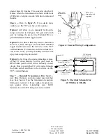
Step  5  —  Figure  4

  shows  how  the  external 

wiring  harness  is  intended  to  be  connected.  To 
use the #4 machine screw to retain the switch to 
the case, a new 3/32" hole must be drilled in the 
mount  boss.  If  floor  pan  clearance  is  a  problem 
then secure the ring terminal to the mount boss on the case to provide a good ground and secure the 
switch to the wiring harness with electrical tape so that it  does not bang around. Some 2004R’s may 
have  an  interface  problem  between  the  TCI

®

  harness  and  the  OEM  case  connector.  To  correct  this 

problem, obtain case connector number 8634383 from a GM dealer. This will allow the TCI harness to 
snap into place. Using 18-gauge wire, run a 12-volt source to the red wire on the harness (Terminal A). 
Connect the vacuum switch to a ported vacuum source on the carburetor or throttle body. (If you find 
that the TCC operation is erratic in  your application, then you may try moving the vacuum source to 
the manifold.) The TCC is  now set to  engage automatically in  4th  gear only  when engine vacuum  is 

Figure 2: 700R4 Competition/Full Manual 

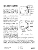
(376010 valve body) Wiring Diagram 

Figure 3: 2004R Street/Strip or 

Competition/Full Manual  

(386010 valve body) Wiring Diagram 


Содержание 376600

Страница 1: ...ow the fluid to be drained After the fluid has drained remove the rest of the bolts and pour out the remaining fluid If your transmission did not come with a drain plug you may want to install a TCI 805800 universal drain plug kit into your pan now that you have the pan off Remember To Dispose Of Used Oil In An Environmentally Safe Way Step 2 Remove original internal wiring harness Carefully disco...

Страница 2: ...ssion case connector into the transmission If you are working with a 700R4 you may want to transfer your OEM plastic wire retainer from your factory wiring harness to the TCI wiring harness in order to keep wires neatly in place Step 5 Figure 4 shows how the external wiring harness is intended to be connected To use the 4 machine screw to retain the switch to the case a new 3 32 hole must be drill...

Страница 3: ... switched 12 volt source Now you may manually turn the lock up system completely on and off Option 3 is for those who desire immediate release of the TCC when braking For this you ll need an OEM brake pedal switch with a normally closed circuit Run your switched 12 volt source through the brake switch and then to the red wire on the TCI external harness Step 7 Reinstall Transmission Pan Install a ...

Страница 4: ...t first going through a pressure switch than it can simply be left in place because that is how the 376600 is wired as well Q What do I do with the other pressure switches that are on my valve body A The simple thing to do is just leave them in place even though they are not hooked up They cannot be removed unless you replace them with 1 8 pipe thread plugs Q What do I do with the extra green wire...

Страница 5: ...rder for the system to work properly the converter clutch valve in the pump must be operable the friction lining and apply piston in the torque converter must be in working order the 0 ring on the end of the input shaft must be in good condition and some valve bodies even have an additional converter clutch valve in them as well which must be functioning It is possible for anyone of the aforementi...

Страница 6: ...ars chances are that there is something else wrong with the transmission The wiring harness is only responsible for turning the torque converter clutch solenoid on and off and it has no effect on the transmission s ability to go into and hold reverse and the four forward ranges Have any problems diagnosed and repaired by a qualified technician immediately Social Media Stay up to date with the late...

Страница 7: ...ity for any errors made in tolerances component selection or installation There is absolutely no warranty on the following Any parts used in racing applications Any product that has been physically altered improperly installed or maintained Any product used in improper applications abused or not used in conjunction with the proper parts Damage due to excessive manifold pressure e g nitrous backfir...

Отзывы: