


TXP Inst. & Maint. Manual: IM-825
39
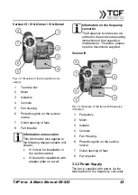
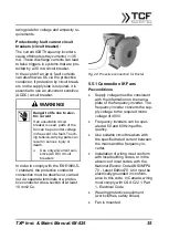
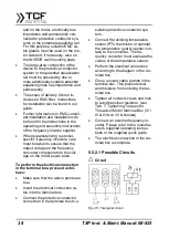
If the main’s phase "L1" is connected to
"U1" and to "W1" the main’s phase "L3",
the impeller rotates to the left(counter-
clockwise).
If the main’s phase "L3" is connected to
"U1" and the main’s phase "L1" to "W1",
the impeller rotates to the right (clock-
Connect the protective conduc-
tor. This is marked with this sym-
bol and is also located in the ter-
A three-way switch is required for the
Indication of the interconnection on
e.g. with the specification on the
the motor may only be used for the
lower voltage (230V, 3-phase cur-
rent!) in the
be connected.
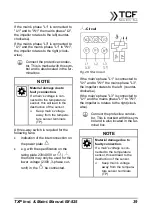
If the main’s phase "L1" is connected to
"U1" and to "W1" the mains phase "L3",
the impeller rotates to the left (counter-
clockwise).
If the main’s phase "L3" is connected to
"U1" and the mains phase "L1" to "W1",
the impeller is rotates to the right(clock-
wise).
Connect the protective conduc-
tor. This is marked with this sym-
bol and is also located in the ter-
minal box.
NOTE
Material damage due to
faulty connection.
If a main’s voltage is con-
nected to the temperature
sensor, this will lead to the
destruction of the sensor.
Keep main’s voltage
away from the tempera-
ture sensor terminals


