background image


ES100 ESS Unit user manual 


17 

4.2 Alarm description and handling 

When  the  protection  action  or  fault  occurs  to  the  system,  the  alarm signal  will  be  shown  through 
the working status indicator on the front panel of the battery. The network management can query 
the specific alarm categories. 

If  the  fault  such  as  single  cell  overvoltage,  charging  over-current,  under-voltage  protection,  high-
temp protection and other abnormalities affects the output, please deal with it according to   

Table4-3 

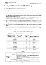
Table 4-3 Main alarm and Protection 

Statue


Alarm category


Alarm


indication


handling


Charging state 

Cell over-voltage 

RED 

Stop charging and find out 

the cause of the trouble 

Over-current 

RED 

Stop charging and find out 

the cause of the trouble 

High temp 

RED 

Stop charging 

Discharge state 

Over-current 

RED 

Stop discharging and find 

out the cause of the trouble 

High temp 

RED 

Stop discharging 

Total voltage 

Under voltage 

RED 

Start charging 

Cell voltage under 

voltage 

RED 

Start charging 

4.3 Analysis and treatment of common faults


Analysis and treatment of common faults in the Table 4-4:   

Table 4-4 Analysis and treatment of common faults 

No.


Fault phenomenon


Reason analysis


Solution


The indicator does not 
respond after it is powered on 

Power switch is broken  Check the power switch 

The DC power supply 

time is too short 

Battery capacity has 
become smaller 

Storage battery replacement 

Battery can not be fully 
charged 

Charging voltage is 
too low 

Adjust the charging voltage to 
53.5V 

The power cable sparks once 
It is powered on and the 
ALM light turns to RED 

Power connection 
short-circuit 

Turn off the battery, check 
the cause of the short circuit 

If you need any technical help or have any questions, please contact the seller in time. 

4.4 Recycle and disposal 

In case a battery (normal condition or damaged) needs disposal or needs recycling, it shall follow 
the local recycling regulation (i.e. Regulation (EC) No 1013/2006 among European Union) to 
process, and using the best available techniques to achieve a relevant recycling efficiency. 

Содержание ES100

Страница 1: ...1 ...

Страница 2: ...1 ES100 ESS Unit User Manual ...

Страница 3: ...1 ES100 ESS Unit User Manual WARNING HIGH VOLTAGE IN SIDE CAUTION THE DC FUSE MUST HAVE BEENTURNED OFF BEFORE SERVICING MADE IN CHINA ...

Страница 4: ...ghts Reserved This product complies with the design requirements of environmental protection and personal safety The storage use and disposal of the products shall be carried out in accordance with the product manual relevant contract or relevant laws and regulations Customer can check the related information on the website of TBB Power Co Ltd when the product or technology is updated Web URL http...

Страница 5: ...ver please contact us if case bulging or another abnormal phenomenon For your safety device shall be ground connected properly before normal use To assure the proper use please make sure parameters among the relevant device are compatible Please do not mixed use batteries from different manufacturers different types and models as well as old and new together Ambient and storage method could impact...

Страница 6: ...otection 8 2 3 2 Current Protection 8 2 3 3 Temperature Protection 8 2 3 4 Other Protection 8 3 Installation and Configuration 9 3 1 Ready for installation 9 3 1 1 Environmental requirements 9 3 1 2 Tools and data 10 3 1 3 Technical preparation 10 3 1 4 Unpacking inspection 11 3 1 5 Engineering coordination 12 3 2 Equipment installation 12 3 2 1 Installation preparation 13 3 2 2 Mechanical install...

Страница 7: ...tures are shown below Suitable for applications with a rated voltage of 48V Built in battery management system for better performance possessing protection functions like over discharge protection over charge protection over current protection abnormal temperature protection Support up to 32 modules in parallel to prolong the standby time Support parameter configuration and data monitoring via TBB...

Страница 8: ...ctions and be aware of the dangers Read the user manual before using The scrapped battery cannot be put into the garbage can and must be professionally recycled After the battery life is terminated the battery can continue to be used after it recycled by the professional recycling organization and do not discard it at will This battery product meets European directive requirements Dangerous goods ...

Страница 9: ...ES100 ESS Unit user manual 3 2 Product Specification 2 1 Size and Weight Table 2 1 ES100 Device size Product Nominal Voltage Nominal Capacity Dimension Weight ES100 DC48V 105Ah 482 6 450 133 4mm 40kg ...

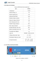
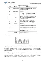
Страница 10: ...current A 105 End of charging current A 1 5 Standard charge voltage V 53 5 Max charge voltage V 54 75 Standard discharge current A 52 5 Maximum discharge current A 105 Final discharge voltage V 42 Cycle Life 90 DOD 6000 cycles life Charging temperature range 0 55 Discharging temperature range 20 55 Storage temperature 20 45 1month 0 35 3months 2 2 1 Front Panel Interface Definition 1 2 3 4 5 6 7 8...

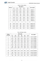
Страница 11: ...cable or parallel negative cable 10 Ground connection point Shell ground connection 2 2 2 Address DIP switch bit1 to bit8 definition bit1 bit5 is used to set the slave address or the number of slaves in parallel according to the master and slave status bit8 is used to set the mark of the master and slave bit6 bit7 are reserved bits Slave setting bit1 bit5 are used to set the slave address Accordin...

Страница 12: ...N ON Address 30 31 ON ON ON ON ON Address 31 Table 2 5 Master setting Slave Quantity DIP switch Description 1 2 3 4 5 8 1 ON OFF OFF OFF OFF ON 2 pcs in parallel 2 OFF ON OFF OFF OFF ON 3 pcs in parallel 3 ON ON OFF OFF OFF ON 4 pcs in parallel 4 OFF OFF ON OFF OFF ON 5 pcs in parallel 5 ON OFF ON OFF OFF ON 6 pcs in parallel 6 OFF ON ON OFF OFF ON 7 pcs in parallel 7 ON ON ON OFF OFF ON 8 pcs in ...

Страница 13: ...ch interface Table 2 6 Port Description CAN PIN4 CANH PIN5 CANL PIN1 3 8 NC PIN2 6 7 NC RS485 1 PIN2 7 485 1A PIN1 3 8 485 1B PIN6 485 2A PIN5 485 2B RS485 2 PIN2 7 485 1A PIN1 3 8 485 1B PIN6 485 2A PIN5 485 2B 2 2 4 SOC light display and corresponding battery capacity Table 2 7 Status Charging Discharging Capacity indicator L1 L2 L3 L4 L1 L2 L3 L4 0 25 flashing OFF OFF OFF ON OFF OFF OFF 25 50 O...

Страница 14: ...eater than the protection value the system will stop supplying power to the loads and disable the output The BMS detects whether there s discharging over current every 1 minute If there is no discharging over current it will be restored to the standby state If there is discharging over current it will continue the protection Also it can resume normal operation by charging 2 3 3 Temperature Protect...

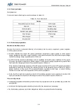
Страница 15: ...ctive measures to avoid touching these cables while operating power equipment The following protective equipment must be worn when installing the battery system Protective gloves Safety goggles Protective shoes Figure 3 1 3 1 1 Environmental requirements Working temperature 20 55 Charging temperature range is 0 55 Discharging temperature range is 20 55 Storage temperature 0 35 Relative humidity 15...

Страница 16: ... DC power interface of the user s PV power generation equipment power supply or other power supply equipment is greater than the maximum charging current of the products used in Table 2 2 If the maximum discharge capacity of the DC power interface of the user s PV power generation equipment is less than the maximum charging current of the products used in Table 2 2 the DC power interface of the us...

Страница 17: ...surface coating of the object Open the package the installation personnel should read the technical documents verify the list according to the configuration table and packing list ensure objects are complete and intact If the internal packing is damaged it should be examined and recorded in detail Packing list is as follows Table 3 2 Item Specification Quantity Figure Battery ES100 48V 105Ah 482 6...

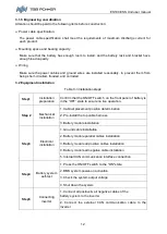
Страница 18: ... Confirm that the ON OFF switch on the front panel of battery is in the OFF state to ensure no live operation Step 2 Mechanical installation 1 Cabinet placement position determination 2 Pre install the top cable harness 3 Battery module installation Step3 Electrical installation 1 Ground cable installation 2 Battery module parallel cables installation 3 Battery module all positive cables installat...

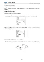
Страница 19: ... Place the battery cell on the cabinet bracket as shown in the figure and push it into the installation position of the cabinet The cabinet structure in the figure is for reference only Figure 3 2 2 Secure the battery cell on the cabinet with a nut through the mounting holes on the top of the battery hanging ears Figure 3 3 Installation method 2 With Simple bracket installation 1 Place the battery...

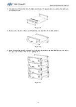
Страница 20: ...to pushing the battery to the buckle position Figure 3 5 3 Place another bracket in the rear of the battery and push it to the buckle position Figure 3 6 4 Stack the required number of battery and bracket combinations as described above and fasten the upper and lower buckles Shown as Figure3 7 Figure 3 7 ...

Страница 21: ...t judgment choose multi meter resistor file probe the same end of positive and negative pole if the resistor shows infinity it means that the cable is available After visually checking the power cable is in good condition connect its postive and negative poles respectively to the positive and negative poles of the battery It is better to add a circuit breaker between the inverter and the battery s...

Страница 22: ...attery has started working normally 3 After confirming the voltage and polarity of the battery close the circuit breaker and turn on the inverter 4 Check whether the inverter indicator and battery indicator communication indicator status indicator are normal If they are normal complete the connection between the battery and the inverter If the indicator lights are abnormal please refer to the inve...

Страница 23: ...rt charging Cell voltage under voltage RED Start charging 4 3 Analysis and treatment of common faults Analysis and treatment of common faults in the Table 4 4 Table 4 4 Analysis and treatment of common faults No Fault phenomenon Reason analysis Solution 1 The indicator does not respond after it is powered on Power switch is broken Check the power switch 2 The DC power supply time is too short Batt...

Страница 24: ...ES100 ESS Unit user manual 18 ...

Отзывы: