27
Model C712
Operating Procedures
121022
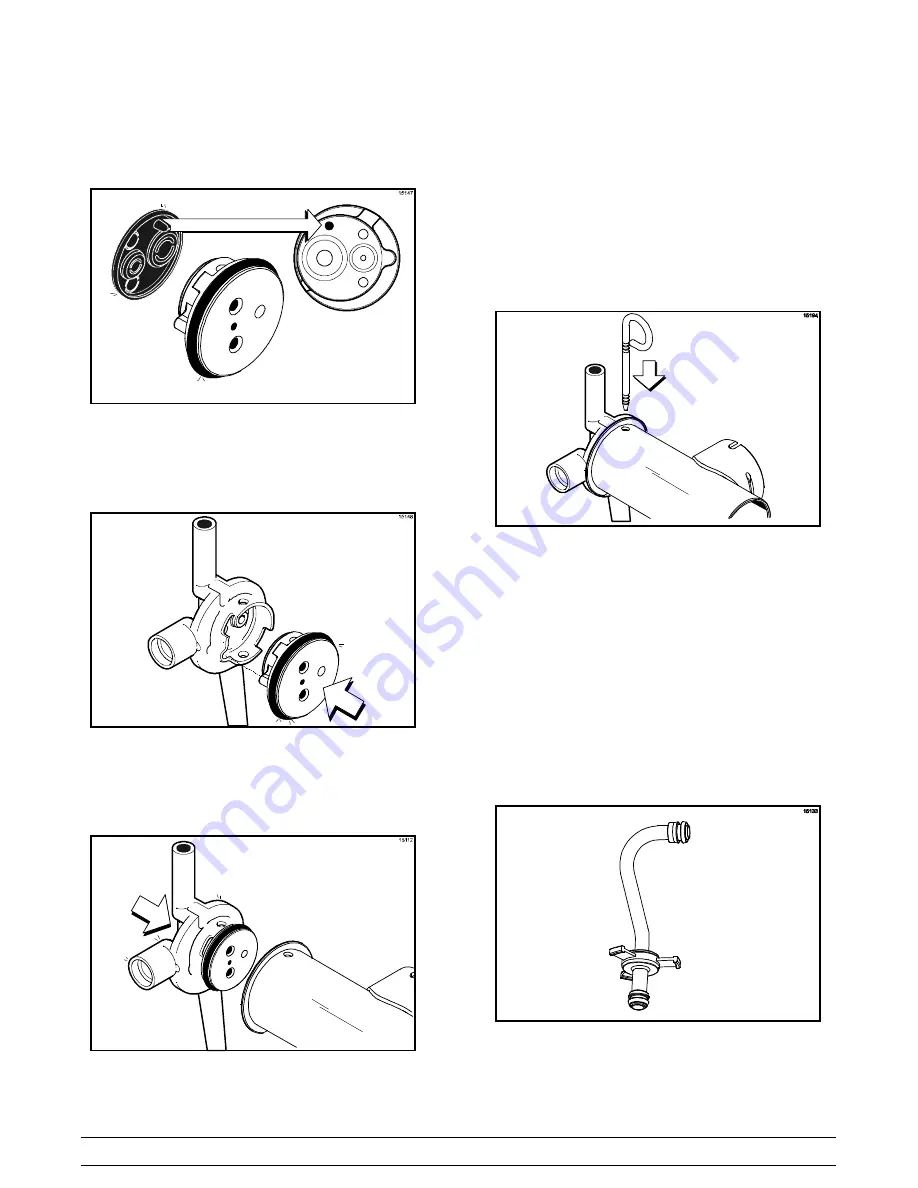
Step 6
Slide the pump valve gasket into the holes on the
cap. DO NOT lubricate the gasket. (See Figure 54.)
Figure 54
Step 7
Insert the valve body cap into the hole in the mix
inlet adapter. (See Figure 55.)
Figure 55
Step 8
Insert the mix inlet assembly into the pump cylinder.
(See Figure 56.)
Figure 56
The adapter must be positioned into the notch
located at the end of the pump cylinder.
Step 9
Secure the pump parts in position by sliding the
retaining pin through the cross holes located at one
end of the pump cylinder. (See Figure 57.)
Figure 57
Note:
The head of the retaining pin should be
located at the top of the pump when installed.
Step 10
Assemble the feed tube assembly. Slide the check
ring into the groove of the feed tube.
(See Figure 58.)
Figure 58
Содержание C712
Страница 11: ...7 Model C712 Operator Parts Identification 121022 Section 4 Operator Parts Identification Model C712 Figure 1 ...
Страница 54: ...Model C712 059898 27 5 13 ...
Страница 55: ...Model C712 059898 33 5 13 ...
Страница 56: ...Model C712 059898 40 5 13 ...
Страница 57: ...Model C712 059898 58 5 13 ...


