Taylor C152 Скачать руководство пользователя страница 87

WIRING DIAGRAMS

6-9 

Model C152 & C161 

Wiring Diagrams 

6

Figure 6-8 Diagram 085584-40S (C161)

Model C161

085584-40S

10/18

Taylor Company

Содержание C152

Страница 1: ...SERVICE MANUAL Model C152 and C161 Soft Serve Freezer 01 23 2017 Original Publication Updated 7 29 2020 Original Service Instructions 085592 S...

Страница 2: ...re considered to be the original set of instructions 2017 Taylor Company Original Publication 085592 S Any unauthorized reproduction disclosure or distribution of copies by any person of any portion o...

Страница 3: ...Troubleshooting Guide 3 2 Electrical Troubleshooting 3 5 Section 4 Parts Warranty Explanation 4 2 Model C152 Operator Parts 4 4 Model C161 Operator Parts 4 5 Model C152 Service Parts 4 6 Model C161 S...

Страница 4: ...ii 085592 S Notes...

Страница 5: ...ion 1 1 1 Model C152 C161 Introduction Safety Introduction Safety Safety Model C152 Specifications Model C161 Specifications General Installation Instructions Environmental Notices Running Specificati...

Страница 6: ...le disconnecting device with a contact gap of at least 0 125 in 3 mm installed in the external installation Machines that are permanently connected to fixed wiring and for which leakage currents may e...

Страница 7: ...sult in personal injury or machine damage WARNING This machine must NOT be installed in an area where a water jet or hose can be used NEVER use a water jet or hose to rinse or clean the machine Failur...

Страница 8: ...0 in 0 mm at the rear If the machine has legs install the skirt provided on the right side of the machine Minimum air clearances must be met to ensure adequate air flow for optimum performance Dimens...

Страница 9: ...12 206 25 21 12 536 45 27 30 693 42 43 00 1092 2 17 38 441 45 53 28 1353 31 50 93 1293 62 13 30 337 82 17 44 442 98 28 17 715 52 TOP VIEW OPERATOR SIDE 29 36 745 75 5 32 135 13 Air Out Far Side Air In...

Страница 10: ...he rear Minimum air clearances must be met to ensure adequate air flow for optimum performance Water Cooled Water inlet and drain connections out of rear 3 8 in 9 5 mm FPT Dimensions Width 21 in 533 m...

Страница 11: ...ONS EQUAL TO PLUS OR MINUS 1 16 INCH 1 5mm DRAWING IS TO BE USED FOR REFERENCE ONLY DO NOT USE FOR STORE CONSTRUCTION LAYOUT 54 53 1385 0 TOP VIEW OPERATOR SIDE 22 12 562 0 20 28 515 1 15 90 404 0 19...

Страница 12: ...erformed in high ambient temperatures of 104 F 40 C at reduced capacities WARNING This machine must NOT be installed in an area where a water jet or hose can be used NEVER use a water jet or hose to r...

Страница 13: ...rsonal injury from electrical shock IMPORTANT This machine is provided with an equipotential grounding lug that is to be properly attached to either the rear of the frame or the underside of the base...

Страница 14: ...er should always flow in this order first through the automatic water valve second through the condenser and third through the outlet fitting to an open trap drain IMPORTANT A backflow prevention devi...

Страница 15: ...potentially hazardous and must be handled with caution NEVER fill any refrigerant cylinder completely with liquid Filling the cylinder to approximately 80 will allow for normal expansion IMPORTANT If...

Страница 16: ...ty to make this fact known to any technicians he she employs It should be noted that Taylor does not warrant the refrigerant used in its machines For example if the refrigerant is lost during the cour...

Страница 17: ...d contactors O O O O O O O O O O O O Thermistors Transducers O O O O O O O O O O O O Labels and insulations O O O O O O O O O O O O Fittings and hardware X O O O O O X O O O O O SJ T 11364 O GB T 2657...

Страница 18: ...Valve Adjustment 1 Place your gauge on the access valve on the suction line located at the compressor 2 Adjust the pressure higher or lower by turning the adjustment screw Clockwise turns raise the p...

Страница 19: ...Section 2 2 1 Model C152 C161 Controls Controls Generation II Control Logic Board Service Tips for Generation II Boards Control Overview Refrigeration Schematic Valve Functions...

Страница 20: ...e two types of thermistor probes used on these freezers The resistance value of the thermistor probes corresponds with the temperature As the temperature increases the probe resistance decreases Appro...

Страница 21: ...oted beater motor s amperage is achieved turn the viscosity adjustment screw counterclockwise slowly until the machine cycles off 8 Draw several samples to verify that the following remain consistent...

Страница 22: ...great Table 2 1 F C Kilo Ohm 10 23 3 118 201 9 22 7 114 394 8 22 2 110 709 7 21 6 107 143 6 21 1 103 692 5 20 5 100 352 4 20 0 97 120 3 19 4 94 085 2 18 8 91 144 1 18 3 88 296 0 17 7 85 536 1 17 2 82...

Страница 23: ...1 6 11 598 72 22 2 11 315 73 22 7 11 039 74 23 3 10 769 75 23 8 10 507 76 24 4 10 250 77 25 0 10 000 78 25 5 9 763 F C Kilo Ohm 79 26 1 9 532 80 26 6 9 306 81 27 2 9 085 82 27 7 8 870 83 28 3 8 659 84...

Страница 24: ...252 148 64 4 2 124 151 66 1 2 004 154 67 8 1 891 157 69 4 1 785 160 71 1 1 687 163 72 8 1 594 166 74 4 1 508 169 76 1 1 427 172 77 8 1 351 175 79 4 1 279 178 81 1 1 212 181 82 8 1 149 184 84 4 1 090...

Страница 25: ...Part I The self test program is initiated by holding down the Pump button on the logic board while simultaneously turning on the power switch The Pump button may or may not be visible Hold down the b...

Страница 26: ...product temperature Mix is warm and Pump is cold 1 The Set Point light is illuminated indicating that the control is reading the soft serve viscosity potentiometer 2 Rotate the adjustment screw back...

Страница 27: ...SER Plate A Dec Includes Board X85289 Model C161 X85775 Model C152 Ribbon Cable 085802 Ribbon Cable 085802 Board Logic Gen 2 11 X69571SER3 Board Logic Gen 2 11 X69571SER3 MIN MAX MIN MAX STANDBY MIN...

Страница 28: ...ic Figure 2 5 C152 20 22 PSI R404A Access Valve One Side Running for C161 C161 15 16 PSI R404A C152 1 C161 2 C152 1 C161 2 C152 0 C161 2 C152 1 C161 2 C152 20 22 PSI R404A C161 15 16 PSI R404A C152 20...

Страница 29: ...he hopper wall Filter Dryer Keeps moisture dirt metal and chips from entering the refrigerant flow control valves Heat Exchanger subcooler Allows the liquid refrigerant to be cooled before it reaches...

Страница 30: ...2 12 CONTROLS Model C152 C161 Controls 2 Notes...

Страница 31: ...Section 3 3 1 Model C152 C161 Troubleshooting Troubleshooting General Troubleshooting Guide Electrical Troubleshooting...

Страница 32: ...is set too fast a Adjust the draw rate 5 oz to 7 1 2 oz 142 g to 213 g of product by weight every 10 seconds b Outdrawing the capacity of the freezing cylinder b The continuous draw rate is approxima...

Страница 33: ...gear box is out of alignment c Re align the gear box 11 Freezing cylinder walls are scored a Missing or worn front bearing a Install or replace the front bearing b The beater assembly is bent b The be...

Страница 34: ...on a The wire harness is running directly behind the buttons causing activation a Remove DEC plate and secure harness below buttons b The wire harness is pinched between the control channel and DEC pl...

Страница 35: ...he power switch beater overload switch compressor high pressure cut out switch overload terminal OL on the power board and COM terminal of the power board and energizes the coil of the compressor cont...

Страница 36: ...3 6 TROUBLESHOOTING Model C152 C161 Troubleshooting 3 Notes...

Страница 37: ...rvice Parts Model C161 Service Parts Beater Door Assembly Model C152 Beater Door Assembly Model C161 Accessories Model C152 Accessories Model C161 X86420 12 Control A 115V 60HZ Model C152 X85977 76 Co...

Страница 38: ...ner s responsibility to make this fact known to any technicians he she employs It should be noted that Taylor does not warrant the refrigerant used in its machine For example if the refrigerant is los...

Страница 39: ...PARTS 4 3 Model C152 C161 Parts 4 Notes...

Страница 40: ...Panel Left 086378 3 Cover A Hopper X49633 SP 4 Tube Feed 035819 5 Panel Rear 086376 6 Panel Right 086377 7 Gasket Base Pan 086306 8 Tray Drip 086312 Item Description Part No 9 Shield Splash 086379 10...

Страница 41: ...Side Left 085262 3 Cover A Hopper 085351 4 Tube Feed 030797 5 Panel Rear 085274 6 Panel A Side Right X69433 7 Gasket Base Pan 055815 SP Item Description Part No 8 Tray Drip 16 7 8L x 4 5 16 085699 9 S...

Страница 42: ...C152 Service Parts Figure 4 3 1 2 3 4 5 6 10 12 8 7 11 9 15 13b 13c 13a 13d 13g 13e 13f 14 16 28 27 26 25 24 52 18 19 20 21 54 53 44 41 42 43 23 22 29 32 33 31 40 36 17 38 37 35 49 48 39 51 30 34 47 4...

Страница 43: ...Screw 10 32X3 8 Serrated 075985 17 Valve Access 1 4 MFL x 1 4 047016 18 Switch Pressure 440 psi 048230 19 Valve Access 1 4 FL x 3 8 044455 20 Compressor 049302 12 21 Sleeve MT Comp AE 039920 22 Gromm...

Страница 44: ...4 FL x 1 4 044404 53 Screw 5 16 18x1 1 2 Hex 001894 54 Washer 5 16 USS Flat CR3 000651 55 Board Logic Gen 2 11 X69571SER3 56 Valve EPR 1 4S 022665 57 Bracket DEC Plate 087311 58 Screw 8 x 1 4 SLTD Hex...

Страница 45: ...C161 Service Parts Figure 4 4 1 2 15 20d 22 20f 21 4 17 11b 13 12 16 20e 6 7 5 10 8 9 11 54 52 47 42 49 37 39 42 40 35 36 34 29 21 19 33 27 31 32 14 29 28 25 30 20a 20c 18 11a 48 41 44 43 38 45 24 23...

Страница 46: ...10x3 8 Slotted Hex 015582 22 Cover Cap Relay Box 055136 23 Screw 10 32x1 2 SERR HWH 036054 24 Nut 10 32 Flange Locknut 020983 25 Motor Fan 50 Watt 029770 27 26 Fan 3 Blade 12 Pull 063397 27 Shroud Co...

Страница 47: ...3 SP1 2 O ring 7 8 OD x 103W 014402 3 Door A 3SPT 1 5qt VALOX X86373 SER 4 Pin A Pivot Short X86374 5 O ring 5 16 OD x 070W 016272 6 Handle Draw 085615 7 Nut Stud 034829 SP Item Description Part No 8...

Страница 48: ...Draw Valve Small H ring 030930 4 Door A 3SPT 1 5qt Valox X56906SER3 5 Pin A Pivot Short X38539 6 O ring 5 16 OD x 070W 016272 7 Handle Draw 085615 8 Nut Stud 056802 SP Item Description Part No 9 Cap...

Страница 49: ...rt no 055492 100 2 oz packs Apply the appropriate Taylor approved food safe lubricant 1 2 3 4 5 6 7 Item Description Part No 1 Pail 6 qt 023348 2 Brush Rear BRG 1 D x 2 LG 013071 3 Brush Double Ended...

Страница 50: ...rt no 055492 100 2 oz packs Apply the appropriate Taylor approved food safe lubricant 1 2 3 4 5 6 7 Item Description Part No 1 Pail 6 qt 023348 2 Brush Rear BRG 1 D x 2 LG 013071 3 Brush Double Ended...

Страница 51: ...9 Clamp Cable Flat Ribbon 046367 10 Bushing Snap 1 ID x 1 1 4OD BL 600288 11 Bushing Snap 1 5 16IDX1 1 2OD 017008 12 Block Terminal 3 Pole 051331 13 Starter 1 Phase 4 0 to 6 5 Amp 066794 12J Item Des...

Страница 52: ...ibbon PWR Relay 069473 60 5 Board Power GEN 1 2 X69574 SER 5a Fuse 063A 250V 5x20mm 051272 6 Screw 6 32x5 8 UNSLTD 041363 7 Contactor 230VAC 1PH 055248 27 8 Overload Thermal 2P 055249 27G Item Descrip...

Страница 53: ...1a Bearing Switch 029244 1b Nut Push On 1 2DIA Shaft 039735 1c Screw 4 40x5 8 SLTD 027219 1d Switch Lever SPDT 027214 1e Insulator Switch 1 64 029099 Item Description Part No 1f Bracket Switch 035524...

Страница 54: ...1a Bearing Switch 029244 1b Nut Push On 1 2DIA Shaft 039735 1c Screw 4 40x5 8 Sltd 027219 1d Switch Lever Spdt 027214 1e Insulator Switch 1 64 029099 Item Description Part No 1f Screw 6 32x3 8 Sltd 00...

Страница 55: ...Start 72 88UF 330V 059757 2 Capacitor Start 161 193UF 25 031790 3 Relay Start Compressor 047067 4 Screw 10x3 8 Slotted Hex 015582 5 Bushing Snap 11 16 ID x 7 8OD 010548 Item Description Part No 6 Str...

Страница 56: ...4 20 PARTS Model C152 C161 Parts 4 Notes...

Страница 57: ...ection 5 5 1 Model C152 C161 Parts List Parts List C152 Standard Machine C152 ROHS Compliant C152 Marine Machine C161 Standard Machine C161 ROHS Compliant C161 Water Cooled Machine C161 Marine Machine...

Страница 58: ...lock Terminal 3 Pole 051331 1 103 Block Terminal 2P L1 N 039421 1 103 Board Logic GEN 2 11 SD CHM DF X69571SER3 1 103 Clamp Cable Ribbon 25C Snap 055033 1 000 Plate Mounting Board 085565 1 103 Screw 6...

Страница 59: ...2 Hex Head 001894 4 000 Compressor TL2 5F R134A 047701 12 1 512 Aux May Use X47701SER1 Complete Kit Cover Terminal Compressor 047739 1 103 Relay Start Compressor 027714 12 1 103 Kit Mounting Compress...

Страница 60: ...Pan C152 086306 1 000 Screw 10X7 16 UNSL TD HWH 066234 10 103 Gasket Base Pan Gear Reducer 025770 SER 1 103 Screw 1 4 20x3 Hex Head Cap 025984 2 000 Screw 1 4 20x3 1 4 Hex Head 025985 2 000 Guide A D...

Страница 61: ...bel Caution Ground Cord Unit 032165 1 000 Label SW Power Off On SYM 052632 1 000 Label Condenser Sharp 059287 2 000 Label Warn Cover 051433 CAN 5 000 Label Warn Elec SGL Small 032717 CAN 2 000 Leg 4 3...

Страница 62: ...Panel Right 086377 1 103 Panel Skirt Air C152 086649 1 103 Only for Machines with legs Trim Corner Rear C152 086375 2 103 Plate A DEC C152 X85775 1 103 Complete w Board Probe A Thermistor FEM 0 25 X3...

Страница 63: ...051542 SP 1 103 Aux Shroud Fan 086381 1 103 Main Spring Comp 720x 063x2 00 023664 1 103 Draw Switch Starter 1 Phase 2 5 to 4 066794 12J 1 103 Overload Thermal 1P 2 5 4 0A 067461 1J 1 103 Button Reset...

Страница 64: ...1 103 Switch A Power Terminal Low Voltage Ground 034455 1 000 Tray Drip 086312 1 103 Tube Feed 150 Danfoss 166 Hole 035819 1 103 Valve Access 1 4FL x 3 8SDR 90 044455 1 103 Valve Access 1 4 MFLX 1 4...

Страница 65: ...1 512 Aux May Use X47701SER2 Complete Kit Relay Start Compressor TL3G 047702 27 1 103 Capacitor Start 60UF 220 275V 047703 1 103 Dryer Cap Tube 026 ID x 8F 048725 1 000 Contactor 230VAC 1PH 50 60HZ 0...

Страница 66: ...TL3G 047702 27 1 103 Aux Relay Start Compressor 048150 1 103 Main Starter 1 Phase 2 5 to 4 066794 27H 1 103 Overload Thermal 1P 2 5 4 0A 067461 1H 1 103 Button Reset 066794 1 1 103 Valve Solenoid 7 6...

Страница 67: ...agram Wiring C152 086047 40 1 000 Harness Trans Relay A 086256 40 1 103 Motor 1 2 HP 059742 40 1 103 Capacitor Run 30 MFD 370V 083338 1 103 Capacitor Start 130 156UF 33 083339 1 103 Motor Fan 23 2W 50...

Страница 68: ...5 12 PARTS LIST Model C152 C161 Parts List Available Separately 5 Optional Items Description Part Number Qty Warr Class Comments KIT A LEG AIR SKIRT C152 X86606 1 103 PANEL SKIRT AIR C152 086649 1 103...

Страница 69: ...nal 3 Pole Green 080968 3 103 Plate End Terminal Block 080969 2 103 Board Logic Gen 2 11 SD CHM DF X69571SER3 2 212 Clamp Cable Ribbon 25C Snap 055033 2 000 Plate Mounting Board 085565 2 103 Screw 6 3...

Страница 70: ...8 4 000 Sleeve Mounting Comp 039924 4 000 Screw 5 16 18x1 1 2 Hex Head 001894 4 000 Compressor PL35G 055187 27 1 512 Aux May Use X55187SER2 Complete Kit Capacitor Start 60UF 220 047703 1 000 Cover Ter...

Страница 71: ...16 OD x 070W 016272 1 000 Pin A Pivot Short X38539 1 103 O ring 5 16 OD x 070W 016272 1 000 Valve Draw 024763 SP1 2 103 O ring 7 8 OD x 103W 014402 4 000 Valve Draw Center 031164 SP 1 103 Seal Draw Va...

Страница 72: ...5 1 103 Switch Toggle 4PDT on None On 037394 1 103 Power Kit A Compressor X55187SER2 1 512 Complete Set Capacitor Start 60UF 220 047703 1 000 Compressor PL35G 055187 27 1 512 Cover Terminal Compressor...

Страница 73: ...or 4 oz 047518 1 000 Lug grounding 4 14GA Wire 017667 1 000 Screw 1 4 20x5 8 Serrated HWH 017522 1 000 Nut 1 4 20 Whiz Flange Lock 017523 1 000 Man Oper 055155 M 1 000 Motor 1 2 HP Remote Caps 055097...

Страница 74: ...FEM 0 25 X31602 38 103 Use X82397 SER Kit A Probe Thermistor IP68 Probe A Mix Square X30922 2 103 Disc Probe SQ Hole 030965 2 103 Spacer Probe SQ Hole 030966 2 103 Pulley 5 7 Pitch DIA x 5 041498 2 10...

Страница 75: ...Shaft 039735 4 000 Screw 4 40x3 4 Unsltd HWH 052569 4 000 Switch Lever SPDT 15A 125 25 027214 2 103 Actuator Switch Plastic 035609 2 103 Draw Switch Arm A Switch X30736 2 103 Draw Switch Spring Comp 7...

Страница 76: ...Valve EXP AUTO 1 4S x1 4 046365 2 103 Boot Valve Expansion 050900 2 000 Valve Sol 1 4 ORFX3 8IN 1 2OD 062019 27 2 103 Line Suction Sol Valve Solenoid 7 64ORF x 1 4 043449 27 2 103 Line Liquid Solenoi...

Страница 77: ...rt Number Qty Warr Class Comments C16127R000 208 230V 60Hz 1PH W C Bristol R404A Standard Machine Description Part Number Qty Warr Class Comments Adaptor 3 8MP x 1 2 Barb 011021 2 103 Bracket A Fittin...

Страница 78: ...61 X69433 SPN 1 103 Panel A LWR Frnt Complet X85729SER1 1 103 Panel Side 161 L 085262 SPN 1 103 Panel Rear 161 AC 085274 SPN 1 103 Diagram Wiring C161 MARI 085584 40M 1 103 Panel Front C161 085678 SPN...

Страница 79: ...C161 Wiring Diagrams Wiring Diagrams Diagram 086047 12 C152 Diagram 086047 12M C152 Diagram 086047 27 C152 Diagram 086047 27M C152 Diagram 086047 40 C152 Diagram 085584 27S C161 Diagram 085584 40M C16...

Страница 80: ...6 2 WIRING DIAGRAMS Model C152 C161 Wiring Diagrams 6 Figure 6 1 Diagram 086047 12 C152 TaylorCompany ModelC152 086047 12 04 18...

Страница 81: ...WIRING DIAGRAMS 6 3 Model C152 C161 Wiring Diagrams 6 Figure 6 2 Diagram 086047 12M C152 TaylorCompany ModelC152 086047 12M 05 18...

Страница 82: ...6 4 WIRING DIAGRAMS Model C152 C161 Wiring Diagrams 6 Figure 6 3 Diagram 086047 27 C152 TaylorCompany ModelC152 086047 27 04 18...

Страница 83: ...WIRING DIAGRAMS 6 5 Model C152 C161 Wiring Diagrams 6 Figure 6 4 Diagram 086047 27M C152 TaylorCompany ModelC152 086047 27M 05 18...

Страница 84: ...6 6 WIRING DIAGRAMS Model C152 C161 Wiring Diagrams 6 Figure 6 5 Diagram 086047 40 C152 TaylorCompany ModelC152 086047 40 04 18...

Страница 85: ...WIRING DIAGRAMS 6 7 Model C152 C161 Wiring Diagrams 6 Figure 6 6 Diagram 085584 27S C161 TaylorCompany ModelC161 085584 27S 10 18...

Страница 86: ...6 8 WIRING DIAGRAMS Model C152 C161 Wiring Diagrams 6 Figure 6 7 Diagram 085584 40M C161 TaylorCompany ModelC161 085584 40M 10 18...

Страница 87: ...WIRING DIAGRAMS 6 9 Model C152 C161 Wiring Diagrams 6 Figure 6 8 Diagram 085584 40S C161 Model C161 085584 40S 10 18 Taylor Company...

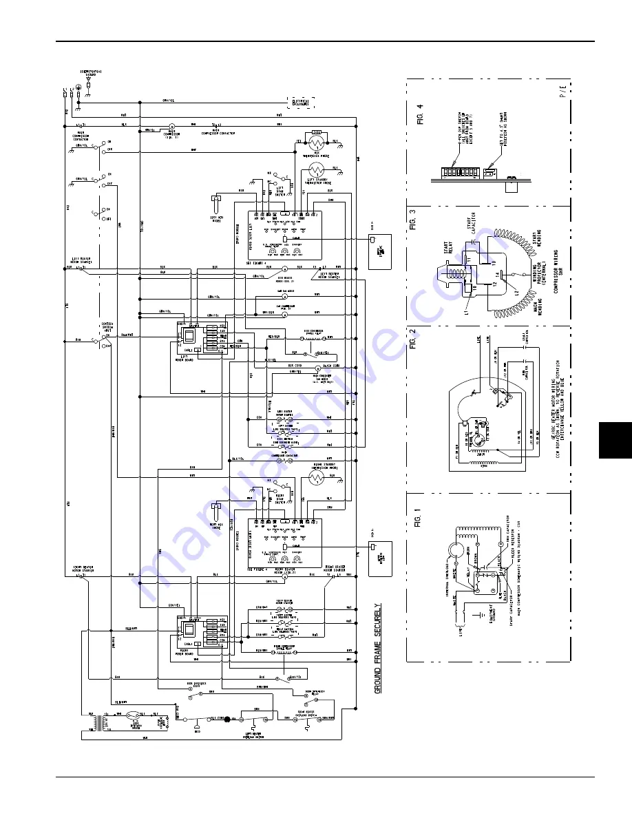
Страница 88: ...6 10 WIRING DIAGRAMS Model C152 C161 Wiring Diagrams 6 Notes...

Отзывы: