background image

 41

Models 750, 751, 754, 774, 791, 794

Limited Warranty on Parts

LIMITED WARRANTY EXCEPTIONS

This limited warranty does not cover:

1.

Labor or other costs incurred for diagnosing, repairing, removing, installing, shipping, servicing or handling of
defective Parts, replacement Parts, or new Parts.

2.

Normal maintenance, cleaning and lubrication as outlined in the Taylor Operator’s Manual, including cleaning
of condensers or carbon and grease buildup.

3.

Required service, whether cleaning or general repairs, to return the cooking surface assemblies, including
the upper platen and lower plate, to an operational condition to achieve proper cooking or allow proper
assembly of release sheets and clips as a result of grease build-up on the cooking surfaces, including but
not limited to the platen and plate, sides of the shroud or top of the shroud.

4.

Replacement of cooking surfaces, including the upper platen and lower plate, due to pitting or corrosion (or
in the case of the upper platen, due to loss of plating) as a result of damage due to the impact of spatulas or
other small wares used during the cooking process or as a result of the use of cleaners, cleaning materials
or cleaning processes not approved for use by Taylor.

5.

Replacement of wear items designated as Class “000” Parts in the Taylor Operator’s Manual, as well as any
release sheets and clips for the Product’s upper platen assembly.

6.

External hoses, electrical power supplies, and machine grounding.

7.

Parts not supplied or designated by Taylor, or damages resulting from their use.

8.

Return trips or waiting time required because a service technician is prevented from beginning warranty
service work promptly upon arrival.

9.

Failure, damage or repairs due to faulty installation, misapplication, abuse, no or improper servicing,
unauthorized alteration or improper operation or use as indicated in the Taylor Operator’s Manual, including
but not limited to the failure to use proper assembly and cleaning techniques, tools, or approved cleaning
supplies.

10.

Failure, damage or repairs due to theft, vandalism, wind, rain, flood, high water, water, lightning, earthquake
or any other natural disaster, fire, corrosive environments, insect or rodent infestation, or other casualty,
accident or condition beyond the reasonable control of Taylor; operation above or below the gas, electrical or
water supply specification of the unit in which a part is installed; or Parts or the units in which they are
installed repaired or altered in any way so as, in the judgment of Taylor, to adversely affect performance, or
normal wear or deterioration.

11.

Any Part purchased over the Internet.

12.

Failure to start due to voltage conditions, blown fuses, open circuit breakers, or damages due to the
inadequacy or interruption of electrical service.

13.

Electricity, gas or other fuel costs, or increases in electricity or fuel costs from any reason whatsoever.

14.

Damages resulting from the use of any refrigerant other than that specified for the unit in which the Part is
installed will void this limited warranty.

15.

Any cost to replace, refill or dispose of refrigerant, including the cost of refrigerant.

16.

ANY SPECIAL, INDIRECT OR CONSEQUENTIAL PROPERTY OR COMMERCIAL DAMAGE OF ANY
NATURE WHATSOEVER.
 Some jurisdictions do not allow the exclusion of incidental or consequential
damages, so this limitation may not apply to you.

This limited warranty gives you specific legal rights, and you may also have other rights which vary from
jurisdiction to jurisdiction.

Содержание 750

Страница 1: ...OPERATOR S MANUAL Model 750 751 754 774 791 794 Soft Serve Freezers Original Operating Instructions 028754 M 2 01 02 Original Publication Updated 12 22 15...

Страница 2: ...l Refrigeration Inc 028754 M Any unauthorized reproduction disclosure or distribution of copies by any person of any portion of this work may be a violation of Copyright Law of the United States of Am...

Страница 3: ...751 Single Spout Door and Beater Assembly 14 Models 754 774 794 Three Spout Door and Beater Assembly 15 Model 791 Three Spout Door and Beater Assembly 16 Accessories 17 Section 5 Important To the Ope...

Страница 4: ...is manual is subject to change without notice Note Only instructions originating from the factory or its authorized translation representative s are considered to be the original set of instructions E...

Страница 5: ...equipment Note All repairs must be performed by an authorized Taylor Service Technician This unit has many sharp edges that can cause severe injuries Site Preparation Review the area the unit is to b...

Страница 6: ...ary for safety In all other areas of the world equipment should be installed in accordance with the existing local codes Please contact your local authorities FOLLOW YOUR LOCAL ELECTRICAL CODES Each u...

Страница 7: ...rigerant In consideration of our environment Taylor uses only earth friendly HFC refrigerants The HFC refrigerant used in this unit is R404A This refrigerant is generally considered non toxic and non...

Страница 8: ...ifies that this product is compliant with the EU Directive as well as other similar legislation in effect after August 13 2005 Therefore it must be collected separately after its use is completed and...

Страница 9: ...or rinse the freezer Failure to follow these instructions may result in serious electrical shock S DO NOT operate the freezer unless it is properly grounded S DO NOT operate the freezer with larger f...

Страница 10: ...ilure to comply may result in personal injury or equipment damage Cleaning and sanitizing schedules are governed by your state or local regulatory agencies and must be followed accordingly Please refe...

Страница 11: ...75 3 Tube A Feed X29429 2 4 Panel Rear 020891 5 Panel Upper Side Right 042317 6 Pan Drip 050766 7 Panel Right Side 050742 8 Shield Splash 022763 9 Tray Drip 013690 Item Description Part No 10 Panel Si...

Страница 12: ...503 7 Panel A Lower Side Right X24424 SER 8 Shield Splash 022763 9 Tray Drip 14 7 8 x 5 1 8 013690 10 Panel Upper Side 024426 11 Panel Service 047170 Item Description Part No 12 Caster Swivel 018794 1...

Страница 13: ...el A Side Lower Right X46448 SER 7 Panel Service 046584 8 Shield Splash 022766 9 Tray Drip 014533 10 Caster Swivel 018794 Item Description Part No 11 Panel Upper Side Left 028822 12 Stud Nose Cone 022...

Страница 14: ...33 10 Caster 4 Swivel 5 8 Stem Brake 034081 11 Panel Upper Side Left 028822 12 Pan Drip 17 1 4 Long 027504 13 Lid with Ladle 1 oz 036575 Item Description Part No 14 Pump A Syrup Tan 053794 TAN 15 O Ri...

Страница 15: ...5 Tube Plunger 032757 6 Insert Plunger 032758 7 Spring Plunger 032761 8 Washer Nylon 032760 9 Plunger 036578 10 Seal Assembly X33057 10a O Ring 13 16 OD x 103 W 019330 11 Body Syrup Pump 047934 12 Nut...

Страница 16: ...T X41820 SP3 2 STUD NOSE CONE 068410 3 PANEL SIDE 069038 4 KIT A COVER HOPPER X68150 5 TUBE A FEED SS 5 32 X29429 2 6 PANEL REAR 041855 ITEM DESCRIPTION PART NO 7 CASTER 4 SWV 5 8 STEM 018794 8 CASTER...

Страница 17: ...ANEL REAR 041855 5 PANEL SIDE LEFT 068691 6 PANEL SIDE RIGHT 068692 7 PANEL SERVICE 064000 8 SHIELD SPLASH 022765 9 TRAY DRIP 021057 ITEM DESCRIPTION PART NO 10 CASTER 4 SWV 5 8 STEM 018794 11 ADAPTOR...

Страница 18: ...EW ADJUSTMENT 069014 1c O RING 1 4OD X 070W 015872 2 NUT STUD FLAT LONG 021508 3 DOOR A 1 SPOUT X51531 10 4 VALVE A DRAW X18303 5 O RING 7 8OD X 070W 014402 6 CAP DESIGN 014218 7 O RING 5 16OD X 070W...

Страница 19: ...OD X 103W SIL 083693 5 CAP DESIGN 1 010 ID 6 POINT 014218 6 PLUG PRIME 028805 7 O RING 3 8 OD X 070W 016137 8 HANDLE A DRAW WHITE X81010 SP 8a HANDLE DRAW WHITE 056248 1 8b SCREW ADJ 5 16 24 056332 8...

Страница 20: ...OD A PIVOT X20683 4 NUT STUD LONG 034382 5 NUT STUD SHORT 034383 6 VALVE A DRAW X69539 7 O RING 7 8 OD X 103W SIL 083693 8 CAP DESIGN 014218 9 DECAL DOOR 3 SPOUT 021521 ITEM DESCRIPTION PART NO 10 DOO...

Страница 21: ...1 x 2 x 17 013073 5 Brush Mix Pump Body 3 x 7 White 023316 6 Sanitizer Stera Sheen Green See note Item Description Part No 7 Pail 10 Qt 751 754 774 791 794 013163 8 Pail 6 Qt 750 023348 9 Deflector B...

Страница 22: ...TOR LIGHT 2 MIX REFRIGERATION KEY 3 STANDBY KEY 4 WASH KEY 5 AUTO KEY 6 POWER ON OFF TOGGLE 7 RESET BUTTON Symbol Definitions To better communicate in the International arena the words on many of our...

Страница 23: ...reezing cylinder to approximately 35_F to 40_F 1 7_C to 4 4_C to prevent overbeating and product breakdown To activate the SHR and CTR press the STANDBY key Remove the air orifice and place the air tu...

Страница 24: ...e hole and place it into the mix inlet hole Every time the draw handle is raised new mix and air from the hopper will flow down into the freezing cylinder This will keep the freezing cylinder properly...

Страница 25: ...he syrup rail Check the water level in the heated syrup topping well Make sure the water is filled to the indicating mark on the bottom of the well The heated rail should have 32 oz 946 2 ml of water...

Страница 26: ...eezing cylinder align the hole at the rear of the beater with the flats on the end of the drive shaft Figure 8 Slide the beater the remainder of the way into the freezing cylinder and over the end of...

Страница 27: ...gs for the Models 754 774 791 and 794 door one for each freezing cylinder Insert the prime plug s into the hole s in the top of the freezer door and push down Figure 12 Step 4 Insert the baffle rod s...

Страница 28: ...adjustable draw handle s Slide the o ring into the groove on the pivot pin and lubricate Figure 16 Slide the fork over the bar in the slot of the draw valve Secure with pivot pin Figure 17 Note Models...

Страница 29: ...Models 791 794 Slide the rear drip pan into the hole in the front panel Step 10 Slide two o rings on one end of the air tube Slide two o rings on the other end of the air tube Figure 21 Slide the sma...

Страница 30: ...794 CAUTION Do not run the machine without product Failure to follow this instruction can result in damage to the machine Sanitizing Step 1 Prepare an approved 100 PPM sanitizing solution examples 2...

Страница 31: ...p 7 When a steady stream of sanitizing solution is flowing from the prime plug opening in the bottom of the freezer door lower the draw handle Draw off all the sanitizing solution Figure 31 Note On th...

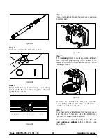
Страница 32: ...cylinder Figure 33 Step 2 Once a steady stream of mix starts to flow from the prime plug opening in the bottom of the freezer door push down the prime plug Figure 34 Step 3 Lubricate the o rings on t...

Страница 33: ...uct must be discarded Drain the product into a pail and properly discard it Repeat steps 1 through 3 for the other side of the freezer on Models 754 774 791 and 794 ALWAYS FOLLOW LOCAL HEALTH CODES Ri...

Страница 34: ...anual or an alternate procedure used in conjunction with a cleaning sanitizing system that has been certified by NSF ALWAYS FOLLOW LOCAL HEALTH CODES Step 1 Prepare a sink with an approved cleaning so...

Страница 35: ...an s and take to the sink for cleaning Note If the drip pan is filled with an excessive amount of mix refer to the Troubleshooting Guide Step 7 Thoroughly brush clean all disassembled parts in the cle...

Страница 36: ...USE OF RERUN make sure the mix rerun is stored in a sanitized covered stainless steel container and used the following day DO NOT prime the machine with rerun When using rerun skim off the foam and di...

Страница 37: ...on may result in electrocution 8 If your machine is water cooled check the water lines for kinks or leaks Kinks can occur when the machine is moved back and forth for cleaning or maintenance purposes...

Страница 38: ...e mix in the mix hopper e Fill the mix hopper with mix 28 f The air orifice is not installed f Install air orifice in air tube 28 2 The product is too stiff a The viscosity needs adjustment a Contact...

Страница 39: ...d a The beater assembly is bent a Call service technician to repair or replace the beater and to correct the cause of insufficient mix in the freezing cylinder b The front bearing is missing or worn o...

Страница 40: ...x in the mix hopper a Fill the mix hopper with mix 28 b The mix inlet hole is frozen up b The mix hopper temperature needs adjustment Call service technician c The air tube is installed incorrectly c...

Страница 41: ...e X Freezer Door Gasket X Front Bearing X Draw Valve O Ring X Pivot Pin O Ring X Prime Plug O Ring X Air Tube O Ring X Air Orifice O Ring X White Bristle Brush 3 x 7 Inspect Replace if Necessary Minim...

Страница 42: ...Refrigeration compressor except service valve Five 5 years Beater motors Two 2 years Beater drive gear Two 2 years Printed circuit boards and Softech controls beginning with serial number H8024200 Tw...

Страница 43: ...Damages resulting from the use of any refrigerant other than that specified on the Product s data label will void this limited warranty 13 Any cost to replace refill or dispose of refrigerant includi...

Страница 44: ...12 Parts Twelve 12 months Class 512 Parts Twelve 12 months Class 000 Parts No warranty Taylor Part 072454 Motor 24VDC C832 C842 Four 4 years LIMITED WARRANTY CONDITIONS 1 If the date of original insta...

Страница 45: ...ty service work promptly upon arrival 9 Failure damage or repairs due to faulty installation misapplication abuse no or improper servicing unauthorized alteration or improper operation or use as indic...

Страница 46: ...IMS FOR LOST SALES LOST PROFITS PRODUCT LOSS PROPERTY DAMAGES OR SERVICE EXPENSES ARE EXPRESSLY EXCLUDED THE EXPRESS WARRANTIES MADE IN THIS LIMITED WARRANTY MAY NOT BE ALTERED ENLARGED OR CHANGED BY...

Отзывы: