background image

Model 490

Table of Contents

Table of Contents - Page 2

Section 7

Important: Operator Checklist

18

. . . . . . . . . . . . . . . . . . . . . . . . . . . . . .

During Cleaning and Sanitizing

18

. . . . . . . . . . . . . . . . . . . . . . . . . . . . . . . . . . . . . . . . .

Troubleshooting Bacterial Count

18

. . . . . . . . . . . . . . . . . . . . . . . . . . . . . . . . . . . . . . . .

Regular Maintenance Checks

18

. . . . . . . . . . . . . . . . . . . . . . . . . . . . . . . . . . . . . . . . . . .

Winter Storage

19

. . . . . . . . . . . . . . . . . . . . . . . . . . . . . . . . . . . . . . . . . . . . . . . . . . . . . . . .

Section 8

Troubleshooting Guide

20

. . . . . . . . . . . . . . . . . . . . . . . . . . . . . . . . . . . .

Section 9

Parts Replacement Schedule

23

. . . . . . . . . . . . . . . . . . . . . . . . . . . . . . .

Section 10

Parts List

24

. . . . . . . . . . . . . . . . . . . . . . . . . . . . . . . . . . . . . . . . . . . . . . . . .

Wiring Diagrams

30

. . . . . . . . . . . . . . . . . . . . . . . . . . . . . . . . . . . . . . . . . . . . . . . . . . . . . .

Note: Continuing research results in steady improvements; therefore, information
in this manual is subject to change without notice.

E

February, 1996 Taylor

All rights reserved.
050271-M

The word Taylor and the Crown design
are registered trademarks in the United States
of America and certain other countries.

Taylor Company
a division of Carrier Commercial Refrigeration, Inc.
750 N. Blackhawk Blvd.
Rockton, IL 61072

Содержание 490

Страница 1: ...Model 490 Shake Freezer Operating Instructions 050271 M 2 96...

Страница 2: ...Number Electrical Specs Voltage Cycle Phase Maximum Fuse Size Amps Minimum Wire Ampacity Amps Part Number E February 1996 Taylor All rights reserved 050271 M The word Taylor and the Crown design are r...

Страница 3: ...gerant 3 Section 2 To the Operator 4 Section 3 Safety 5 Section 4 Operator Parts Identification 7 Model 490 7 Beater Door Asssembly 8 Section 5 Important To the Operator 9 Indicator Lights Add Mix Mix...

Страница 4: ...ement Schedule 23 Section 10 Parts List 24 Wiring Diagrams 30 Note Continuing research results in steady improvements therefore information in this manual is subject to change without notice E Februar...

Страница 5: ...e to follow this instruction may result in personal injury or death from electrical shock or hazardous moving parts as well as poor performance or damage to the equipment Note All repairs must be perf...

Страница 6: ...ncoming water connection side Please refer to the applicable National State and local codes for determining the proper configuration Electrical Connections In the United States this equipment is inten...

Страница 7: ...the diagram printed on the motor Electrical connections are made directly to the terminal block provided in the main control box Refrigerant In consideration of our environment Taylor proudly uses on...

Страница 8: ...3 2005 Therefore it must be collected separately after its use is completed and cannot be disposed as unsorted municipal waste The user is responsible for returning the product to the appropriate coll...

Страница 9: ...ions may result in serious electrical shock S DO NOT operate the freezer unless it is properly grounded S DO NOT operate the freezer with larger fuses than specified on the freezer data label S DO NOT...

Страница 10: ...comply may result in personal injury or equipment damage Cleaning and sanitizing schedules are governed by your state or local regulatory agencies and must be followed accordingly Please refer to the...

Страница 11: ...ntification Model 490 Figure 1 Item Description Part Number 1 Hopper Cover A X38458 SER 1a Knob Mix Cover 025429 2 Gasket Hopper Cover 038375 3 Deflector Air 048549 Item Description Part Number 4 Coll...

Страница 12: ...Assembly X30272 SER 2 Gasket Door 016672 3 Front Bearing 013116 4 Beater Assembly X46233 5 Scraper Blade 046237 6 Clip Scraper Blade 046238 Item Description Part No 7 Beater Shaft 036412 8 Seal Beater...

Страница 13: ...echanism protects the beater motor from an overload condition Should an overload occur the overload mechanism will discontinue machine operation To properly reset the freezer place the control switch...

Страница 14: ...te When lubricating parts use an approved food grade lubricant Example Taylor Lube Step 1 Install the drive shaft Slide the o ring into the first groove on the drive shaft Lubricate the groove and the...

Страница 15: ...freezing cylinder Figure 6 Make sure the beater assembly is in position over the drive shaft Turn the beater slightly to be certain that the beater is properly seated When in position the beater will...

Страница 16: ...ugh the beater in the freezing cylinder With the door seated on the freezer studs install the handscrews Tighten equally in a criss cross pattern to insure the door is snug Figure 11 Rotate the draw v...

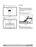
Страница 17: ...ion examples 2 1 2 gal 9 5 liters of Kay 5R or 2 gal 7 6 liters of Stera SheenR USE WARM WA TER AND FOLLOW THE MANUFACTURER S SPECIFICATIONS Step 2 Pour the sanitizing solution into the hopper and all...

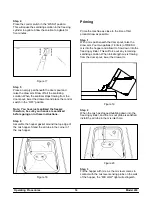
Страница 18: ...ound the top edge of the mix hopper Stand the air tube in the corner of the mix hopper Figure 18 Priming Prime the machine as close to the time of first product draw as possible Step 1 With a mix pail...

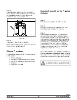
Страница 19: ...ace the control switch in the OFF position Step 2 Remove the hopper cover gasket and air tube Take these items to the sink for cleaning Step 3 If local health codes permit the use of rerun place a san...

Страница 20: ...and raise the draw arm Draw off all the cleaning solution When the solution stops flowing from the door spout lower the draw arm and place the control switch in the OFF position Disassembly Note Failu...

Страница 21: ...rear o ring first This will allow the o ring to slide over the forward o rings without falling into the open grooves Step 5 Thoroughly brush clean all disassembled parts in the cleaning solution makin...

Страница 22: ...CODES PERMIT THE USE OF RERUN make sure the mix rerun is stored in a sanitized covered stainless steel container and used the following day DO NOT prime the machine with rerun When using rerun skim of...

Страница 23: ...be replaced only by an authorized Taylor mechanic Winter Storage To protect the freezer during the winter months when the place of business is closed it is important that certain precautions be follo...

Страница 24: ...er with mix 14 2 Product too stiff a EVC control set incorrectly a Contact service technician b Inadequate mix in hopper b Fill hopper with mix 14 3 Product too soft a EVC control set incorrectly a Co...

Страница 25: ...a Missing or worn drive shaft seal on drive shaft a Install or replace regularly 23 b Drive shaft seal installed inside out b Install seal properly 10 c Missing or worn drive shaft o ring c Install or...

Страница 26: ...ROBABLE CAUSE REMEDY PAGE REF 11 Product not feeding into freezing cylinder a Inadequate level of mix in the mix hopper a Fill the mix hopper with mix 14 b Mix inlet hole frozen b Mix hopper temperatu...

Страница 27: ...de X Drive Shaft Seal X Drive Shaft O Ring X Freezer Door Gasket X Front Bearing X Draw Valve O Ring X White Bristle Brush 3 x 7 Inspect Replace if Necessary Minimum White Bristle Brush 1 1 2 x 2 Insp...

Страница 28: ...MP FEED T 013072 000 BRUSH DRAW VALVE 1 1 2 OD X 3 014753 000 S N K8054099 UP REPLACES 013073 BETTER FIT BRUSH MIX PUMP BODY 3 X7 WHITE 023316 000 COMPRESSOR L63B562BBCB 048727 27E 512 S N K5085883 UP...

Страница 29: ...8549 103 DIAGRAM WIRING 390 047730 27 000 208 230V 60HZ 1PH DIAGRAM WIRING 390 047730 33 000 208 230V 60HZ 3PH DOOR PARTIAL 1 SPOUT SHAKE X30272 SER 103 GASKET DOOR 5 177ID X 5 938OD 016672 000 KNOB D...

Страница 30: ...REPLACES X47219 27 135 LOUVER SIDE TOP 051192 103 LUBRICANT SUPER TAYLOR 047518 000 MOTOR 1 2 HP 059742 27 212 GE S N K6035004 UP CAPACITOR RUN 10UF 370V 059998 103 CAPACITOR START 72 88UF 330V 059757...

Страница 31: ...50 60 066795 33 103 RELAY DPDT 20 A 24VAC 026581 03 103 SANITIZER KAY 5 CASE 125 PCKTS 041082 000 SENSOR A EVC SLUSH 15 X66231M 103 S N K8027256 UP SENSOR A EVC SLUSH 15 X44354 103 S N K8025458 PRIOR...

Страница 32: ...8777 103 CLAMP HOSE ADJ 7 16 X 25 32 010031 000 CONDENSER WC SPIRAL 11 1 2 OD 049309 103 COUPLING 3 8 NPT BLACK PIPE 010878 103 HOSE RUBBER 1 2 ID X 7 8 OD R50200 000 MOTOR FAN 9 WATT 1550RPM CW 01276...

Страница 33: ...12 S N K8115636 PRIOR 220 240V 50HZ 1PH COPELAND CAPACITOR RUN 20UF 370V 023606 103 CAPACITOR START 64 77UF 250V 051960 103 RELAY START COMPRESSOR 051957 40 103 FUSE 1 AMP BUSS GLR 1 050449 000 HOLDER...

Страница 34: ...Model 490 047730 27 Rev 10 08...

Страница 35: ...Model 490 047730 33 Rev 10 08...

Отзывы: