background image

Models 369/370/371

9

ENGLISH

(see figure 12)

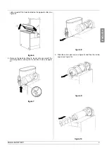
4 - Fit bowl gasket around its seat.

Note: the largest brim of gasket must face against the rear
wall (see figure 14).

figure 14

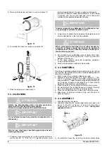
5 - Carefully insert the auger into the evaporator use caution

to prevent it from hitting the rear wall (see figure 15).

figure 15

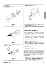
6 - Install the outer spiral. Slide it over the evaporator until its

front notch engages with the exposed end of the auger
shaft (see figure 16).

figure 16

7 - Push the bowl toward the rear wall of the unit until it fits

snugly around the gasket and its front fastening hooks are

properly engaged (see figure 17).

figure 17

8 - On 369 MODEL install the lateral tray by reversing the

disassembly steps (see figure 6).

9 - Use fresh product to chase any remaining sanitizer from

the bottom of the bowl(s). Drain this solution. Do not rinse
out the machine.

5. 4 IN-PLACE SANITIZATION

The In-Place Sanitization prior to starting the machine may be
performed prior to starting the machine, if needed, this should
only be performed, in addition to the Disassembled Parts
Sanitization, but never in lieu of it.

1 - Prepare two gallons of a warm (45-60°C / 120-140 °F)

s a n i t i z i n g   s o l u t i o n   ( 1 0 0   P P M   a v a i l a b l e   c h l o r i n e
concentration or 1 spoon of sodium hypoclorite diluted with
half a gallon of water) according to your local Health
Codes and manufacturer’s specifications.

2 - Pour the solution into the bowl(s).

3 - Using a brush suitable for the purpose, wipe the solution

on all surfaces protruding above the solution-level and on
the underside of the top cover(s).

4 - Install the top cover(s) and operate the unit. Allow the

solution to agitate for about two minutes. Drain the solution
out of the bowl(s).

5 - Use fresh product to chase any remaining sanitizer from

the bottom of the bowl(s). Drain this solution. Do not rinse
out the machine.

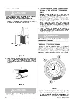
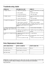
6 ROUTINE MAINTENANCE

1 -

Daily: 

inspect the machine for signs of product leaks past

seals and gaskets. If proper assembly does not stop leaks
around seals or gaskets, check for improper lubrication,
worn or damaged parts. Replace parts as needed.

2 -

Monthly on 369, 370 and 371 models: 

remove the dust

ATTENTION

A damaged power cord must be replaced by an
authorized service agent. Failure to comply main result
in electric shock.

Содержание 369

Страница 1: ...OPERATOR S MANUAL Granita Merchandising Freezers Model 369 FBM 1P Model 370 FBM 2 Model 371 FBM 3 ROCKTON ILLINOIS 61072...

Страница 2: ...____________ Parts ___________________________________________________________________ Date of Installation _________________________________________________________ Model Number _____________________...

Страница 3: ...417 U S A 5 713 214 U S A 5 906 105 TABLE OF CONTENTS 1 TECHNICAL CHARACTERISTICS 4 2 INTRODUCTION 4 3 INSTALLATION 4 4 TO OPERATE SAFELY 5 5 OPERATING PROCEDURES 5 5 1 DESCRIPTION OF CONTROLS 5 5 2...

Страница 4: ...ce with electrical codes in force in your area suitable to at least 10 Amp 250 Volt 220 230 Volts 50 60 Hz areas and 20 Amp 250 Volt 100 115 Volts 50 60 Hz areas applications Should you prefer to conn...

Страница 5: ...r thickness The mixers will continue to turn 5 1 DESCRIPTION OF CONTROLS The dispenser is equipped with a power switch and a light switch In addition each bowl is individually operated by a mixer refr...

Страница 6: ...hat no blocks of ice have been formed if so they are to be removed before the unit is switched on Overnight operation in drink mode also eliminates possible ice accumulation from condensation around t...

Страница 7: ...posite side see figure 6 figure 6 3 Remove the bowl by lifting its faucet side up and off the fastening hooks see figure 7 and slide it out see figure 8 figure 7 figure 8 4 Slide the outer spiral out...

Страница 8: ...available chlorine concentration or 1 spoon of sodium hypoclorite diluted with half a gallon of water according to your local Health Codes and manufacturer s specifications 3 Place the parts in the sa...

Страница 9: ...addition to the Disassembled Parts Sanitization but never in lieu of it 1 Prepare two gallons of a warm 45 60 C 120 140 F sanitizing solution 100 PPM available chlorine concentration or 1 spoon of sod...

Страница 10: ...ce the entire parts with original spare parts from the supplier 5 In order to prevent any damages to the dispenser all plastics parts must be lubricated only with grease supplied by the manufacturer o...

Страница 11: ...imer by pushing out on the tabs C that correspond to the hours desired to defrost Each tab represents 15 minutes A minimum of four to eight hours are required to defrost frozen beverage depending on a...

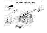
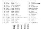
Страница 12: ...OPERATOR PARTS IDENTIFICATION MODEL 369 370 371 2471_01 V 3 5 04I09...

Страница 13: ...210 O Ring Flange Red 71 057894 27 Light Amber Warning 230V 50Hz 16 048160 Panel front 371 42 052211 Flange Gear Motor Plastic 71 057894 27 Light Amber Warning 240V 50Hz 17 046471 Cover Switch box 43...

Страница 14: ...ll 2 21 052054 Spring Viscosity spring 2 057902 Stator Gear Motor 240V 50Hz 11 052049 Spacer 1 5 MM 22 049027 Rotor Gear Motor 2 046514 12 Stator Gear Motor 115V 60Hz 12 046523 Gear Third 23 049026 Pi...

Страница 15: ...fully follow directions for mixing product b Adjust viscosity accordingly c The power switch must be in I and the mix refrigeration switch in the I or II position 4 The freezer will not operate with t...

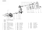
Страница 16: ...046445 M 2471_01 R0 4 04I09...

Отзывы: