Taylor 161 Скачать руководство пользователя страница 5

1

Model 161

To the Installer

131122

Section 1

To the Installer

The following information has been included in the

manual as safety and regulatory guidelines. For

complete installation instructions, please see the

Installation Checklist.

Installer Safety

In all areas of the world, equipment should be

installed in accordance with existing local codes.

Please contact your local authorities if you have any

questions.

Care should be taken to ensure that all basic safety

practices are followed during the installation and

servicing activities related to the installation and

service of Taylor equipment.

S

Only authorized Taylor service personnel

should perform installation and repairs on the

equipment.

S

Authorized service personnel should consult

OSHA Standard 29CFRI910.147 or the

applicable code of the local area for the

industry

standards

on

lockout/tagout

procedures before beginning any installation

or repairs.

S

Authorized service personnel must ensure

that the proper PPE is available and worn

when required during installation and service.

S

Authorized service personnel must remove all

metal jewelry, rings, and watches before

working on electrical equipment.

The main power supply(s) to the freezer must

be disconnected prior to performing any repairs.

Failure to follow this instruction may result in personal

injury or death from electrical shock or hazardous

moving parts as well as poor performance or damage

to the equipment.

Note: All repairs must be performed by an

authorized Taylor Service Technician.

This unit has many sharp edges that can

cause severe injuries.

Site Preparation

Review the area where the unit will be installed before

uncrating the unit. Make sure that all possible hazards

to the user and the equipment have been addressed.

For Indoor Use Only:

This unit is designed to operate

indoors, under normal ambient temperatures of

70

_

-75

_

F (21

_

-24

_

C). The freezer has successfully

performed in high ambient temperatures of

104

_

(40

_

C) at reduced capacities.

This unit must

NOT

be installed in an area

where a water jet or hose can be used.

NEVER

use a

water jet or hose to rinse or clean the unit. Failure to

follow this instruction may result in electrocution.

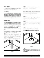
This unit must be installed on a level surface

to avoid the hazard of tipping. Extreme care should be

taken in moving this equipment for any reason. Two or

more persons are required to safely move this unit.

Failure to comply may result in personal injury or

equipment damage.

Uncrate the unit and inspect it for damage. Report any

damage to your Taylor Distributor.

This piece of equipment is made in the USA and has

USA sizes of hardware. All metric conversions are

approximate and vary in size.
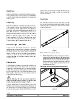
Air Cooled Units

DO NOT

obstruct air intake and discharge openings:

The Model 161 requires 6” (152 mm) on both sides,

and 0” at the rear. Install the skirt provided on the right

side of the unit. Minimum air clearances must be met

to assure adequate air flow for optimum performance.

Содержание 161

Страница 1: ...OPERATOR S MANUAL Model 161 Soft Serve Freezer Original Operating Instructions 055155 M 8 14 08 Original Publication Updated 7 8 14...

Страница 2: ...l Refrigeration Inc 055155 M Any unauthorized reproduction disclosure or distribution of copies by any person of any portion of this work may be a violation of Copyright Law of the United States of Am...

Страница 3: ...Cycle 1 Ph Supplied With Cord and Plug 3 Section 2 To the Operator 4 Section 3 Safety 5 Section 4 Operator Parts Identification 7 Model 161 7 Beater Door Assembly 8 Accessories 9 Section 5 Important...

Страница 4: ...ithout notice Note Only instructions originating from the factory or its authorized translation representative s are considered to be the original set of instructions E 2008 Carrier Commercial Refrige...

Страница 5: ...ng parts as well as poor performance or damage to the equipment Note All repairs must be performed by an authorized Taylor Service Technician This unit has many sharp edges that can cause severe injur...

Страница 6: ...dered necessary for safety Compliance therewith and proper maintenance will result in an installation essentially free from hazard In all other areas of the world equipment should be installed in acco...

Страница 7: ...e beater motor Follow diagram printed on motor Electrical connections are made directly to the terminal block provided in the splice boxes which are mounted mid level on the frame channel on the sides...

Страница 8: ...August 13 2005 Therefore it must be collected separately after its use is completed and cannot be disposed as unsorted municipal waste The user is responsible for returning the product to the appropri...

Страница 9: ...nse the freezer Failure to follow these instructions may result in serious electrical shock S DO NOT operate the freezer unless it is properly grounded S DO NOT operate freezer with larger fuses than...

Страница 10: ...onal injury or equipment damage Cleaning and sanitizing schedules are governed by your Federal State or local regulatory agencies and must be followed accordingly Please refer to the cleaning section...

Страница 11: ...06 2 PANEL SIDE LEFT 058491 3 GASKET HOPPER COVER 037042 4 COVER A HOPPER X37963 SER 4a KNOB MIX COVER 025429 5 TUBE FEED 030797 6 PANEL REAR 058492 ITEM DESCRIPTION PART NO 7 PANEL A SIDE RIGHT X5849...

Страница 12: ...930 4 DOOR A 3SPT 1 5QT VALOX X56906SER1 5 PIN A PIVOT 168 SHORT X38539 6 O RING 5 16 OD X 070W 016272 7 HANDLE DRAW VALVE 030564 8 NUT STUD 056802 ITEM DESCRIPTION PART NO 9 CAP DESIGN 1 010 ID 6 PT...

Страница 13: ...DED 013072 4 BRUSH DRAW VALVE 1 OD X 2 X 17 013073 ITEM DESCRIPTION PART NO 5 BRUSH MIX PUMP BODY 3 X7 WHITE 023316 6 LUBRICANT TAYLOR 4 OZ 047518 7 KIT A TUNE UP X31167 SANITIZER KAY 5 25 PKTS SEE NO...

Страница 14: ...CATOR LIGHT MIX LOW 7 RESET BUTTON Symbol Definitions To better communicate in the International arena the words on many of our operator switchesand keyshave symbols to indicate their functions Your T...

Страница 15: ...end with the mix delivery hole is positioned at the top Install the end without the mix delivery hole into the mix inlet hole in the bottom of the hopper This will prevent mix from entering the freezi...

Страница 16: ...he front of the unit The reset protects the beater motor from an overload condition If an overload occurs the reset mechanism will trip To properly reset the freezer press the AUTO key to cancel the c...

Страница 17: ...the mix delivery hole is placed in the mix inlet hole to prevent mix from entering the freezing cylinder Feed Tube Position During Standby Operation Figure 9 Note Make sure the level of mix is below t...

Страница 18: ...chine sanitize them and prime the machine with fresh mix in preparation to serve your first portion Figure 10 If you are disassembling the machine for the first time or need information to get to the...

Страница 19: ...both hands hold the sides of the freezer door and insert the baffle rods into the center of the beater assemblies The white guide bearings must fit securely in the holes of the drive shafts Step 7 Fin...

Страница 20: ...draw valves into the freezer door from the bottom until the slot in the draw valves comes into view Figure 18 Step 11 Slide the o ring onto each pivot pin and lubricate Figure 19 Step 12 Slide the tip...

Страница 21: ...lash shield under the freezer door Figure 22 Step 16 Install the drip pans Figure 23 Sanitizing Step 1 Prepare an approved 100 PPM sanitizing solution examples 2 1 2 gal 9 5 liters of Kay 5R or 2 gal...

Страница 22: ...er to be agitated Allow it to agitate for five minutes Figure 28 Step 6 Place an empty pail beneath the door spouts Momentarily open the center draw valve to sanitize the center door spout Open the re...

Страница 23: ...S Necessary brushes provided with machine S Cleaner S Single service towels Draining Product From the Freezing Cylinder Step 1 Press the AUTO key to cancel operation Press the MIX REF key to cancel h...

Страница 24: ...cause the cleaning solution in the freezing cylinder to agitate Step 5 Place an empty pail beneath the door spouts and raise the draw valve Draw off all the cleaning solution When the solution stops...

Страница 25: ...s Step 4 Remove the large o rings front bearings and guide bearings from the back of the freezer door Step 5 Return to the machine with a small amount of cleaning solution With the black bristle brush...

Страница 26: ...cleaning solution on the brush j 5 IF LOCAL HEALTH CODES PERMIT THE USE OF RERUN make sure the mix rerun is stored in a sanitized covered stainless steel container and is used the following day DO NOT...

Страница 27: ...lines for kinks or leaks Kinks can occur when the machine is moved back and forth for clean ing or maintenance purposes Deteriorated or cracked water lines should be replaced only by an authorized Ta...

Страница 28: ...the fuse f The freezer door is incorrectly assembled f See Operating Procedures for proper installation 15 g Product is being drawn off in excess of the freezer s capacity g Stop drawing product and...

Страница 29: ...in rear drip pan a A worn or defective o ring is on the beater drive shaft a Replace o rings every 3 months 27 b The rear shell bearing is worn b Contact service technician c Incorrect lubricant was...

Страница 30: ...eded for the freezer to operate properly b An extension cord has been placed between the power cord and the wall receptacle b If the extension cord is used it must match the power cord in size of circ...

Страница 31: ...ing X 2 Freezer Door Front Bearing X 2 Freezer Door Guide Bearing X 2 Draw Valve O Ring X 4 Center Draw Valve Seal X 1 Pivot Pin O Ring X 2 Black Bristle Brush 1 x 2 Inspect Replace if Necessary Minim...

Страница 32: ...ion compressor except service valve Five 5 years Beater motors Two 2 years Beater drive gear Two 2 years Printed circuit boards and Softech controls beginning with serial number H8024200 Two 2 years P...

Страница 33: ...esulting from the use of any refrigerant other than that specified on the Product s data label will void this limited warranty 13 Any cost to replace refill or dispose of refrigerant including the cos...

Страница 34: ...elve 12 months Class 512 Parts Twelve 12 months Class 000 Parts No warranty Taylor Part 072454 Motor 24VDC C832 C842 Four 4 years LIMITED WARRANTY CONDITIONS 1 If the date of original installation of...

Страница 35: ...work promptly upon arrival 9 Failure damage or repairs due to faulty installation misapplication abuse no or improper servicing unauthorized alteration or improper operation or use as indicated in the...

Страница 36: ...ST SALES LOST PROFITS PRODUCT LOSS PROPERTY DAMAGES OR SERVICE EXPENSES ARE EXPRESSLY EXCLUDED THE EXPRESS WARRANTIES MADE IN THIS LIMITED WARRANTY MAY NOT BE ALTERED ENLARGED OR CHANGED BY ANY DISTRI...

Страница 37: ...SD CHM DF X65971 SER 1 212 SWITCH MEMBRANE 5 POSITION 043217 2 000 BOARD POWER GEN 1 2 X69574 SER 2 212 REPLACED X32326 SER U D 225 FUSE 063A 250V 5X20MM SLO BLO 051272 2 000 BOLT CARRIAGE 1 4 20X3 4...

Страница 38: ...7155 1 103 DANFOSS DRYER CAP TUBE 021 ID X 9F 055522 1 000 DANFOSS SCREW 1 4 20X1 HEX HEAD C 017254 4 000 CONDENSER AC 12LX16HX2 5T 048935 1 103 CONDENSER AC 7X6X1 25 2 ROW 027155 1 103 CONTACTOR 230V...

Страница 39: ...X17 75X7 1 042703 1 000 GASKET BASE PAN 161 055815 1 000 SCREW 10X7 16 UNSL TD HWH 066234 12 000 GASKET BASE PAN GASKET HOPPER COVER 8QT 037042 1 000 GEAR A REDUCER 4 TO 1 SERVICE 025770 SER 2 212 SCR...

Страница 40: ...000 LABEL SW POWER OFF ON SYM 052632 1 000 LABEL WARN CONDENSER SHAR 059287 2 000 LABEL WARN COVER 051433 5 000 LABEL WARN ELEC TW SMALL 032718 1 000 LUBRICANT TAYLOR 4 OZ 047518 1 000 MAN OPER 161 0...

Страница 41: ...00UA TO 7A 1 8HP 052111 03 1 103 S N M1096647 UP U D 221 RELAY DPDT 100UA TO 7A 052111 76 2 103 S N M1096647 UP U D 221 SOCKET RELAY FOR USE W 05 052112 3 103 S N M1096647 UP U D 221 SANITIZER STERA S...

Страница 42: ...18 25 015850 L 13 103 TERMINAL FEM SP INS 16 14 023959 L 3 000 TERMINAL LOW VOLTAGE GROU 034455 2 000 TRAY DRIP 16 7 8L X 4 15 020157 SP 1 103 TUBE FEED 166 HOLE SS TM 030797 2 103 VALVE ACCESS 1 4FL...

Страница 43: ...D 42 066395 95 1 103 220 240V 50HZ 1PH ROHS INDICATOR DIGITAL TEMP SO 051356 2 DIGITAL THERMOMETER DIAGRAM WIRING 161 063820 40S 1 000 220 240V 50HZ 1PH DVD OPS TRAIN VIDEO TAYLO 037665 DVD 1 000 220...

Страница 44: ...GHT 161 X58490 SPN 1 103 PANEL LOWER FRONT 161 058493 SPN 1 103 PANEL REAR 161 AC 058492 SPN 1 103 PANEL SIDE LEFT 161 058491 SPN 1 103 PLATE DEC 161 GENII 055512 SPN 1 103 SHIELD SPLASH 5454 8 752 02...

Страница 45: ...68 X31167 1 000 LABEL ATTN SVC ENG CHINES 015068 CH 2 000 LABEL CAUTION GRD PERM CH 032164 CH 1 000 LABEL DOOR MOVE PART CHINESE 032749 CH 1 000 LABEL WARN COVER CHINESE 051433 CH 5 000 LABEL WARN ELE...

Страница 46: ...MISTOR PROBE BLK BLK WHT BLK BRN WHT GRN YEL GRN YEL MAIN COMPRESSOR CONTACTOR MAIN COMPRESSOR CONTACTOR M T3 L3 LEFT BEATER MOTOR FIG 2 BLK WHT LEFT BEATER MOTOR STARTER BLK L1 T1 BLK BLU BLU WHT LEF...

Страница 47: ...BOARD WHT C GRN YEL C GRN YEL RIGHT BEATER MOTOR FIG 2 4 GREEN YELLOW ORN M MAIN CONDENSER BLACK CORD FAN MOTOR A C UNIT ONLY BLK CORD M SHR FAN MOTOR WHT BLK WHT ON OFF ON OFF ON OFF YEL ON OFF 13 1...

Отзывы: