Taylor-Dunn R0-380-36 Скачать руководство пользователя страница 96

Hardware

Page  96

R-380 DC System

MR-380-03

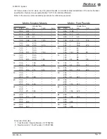
Generic Torque Values

All torque values are for clean dry zinc plated threads in noncritical steel assemblies of the same hardness 

specification. Reduce torque approximately 10-15% for lubricated threads.

Refer to the service section assembly procedure for critical torque values.

Imperial (inch), Foot Pounds

   Grade, 

SAE 

Dia.  Pitch    2 

   5 

 8 

L9

#4 40  *  * 

*

#6 32  *  * 

*

#8 32  *  * 

*

#10 32  * 

*

#12 32  * 

*

1/4 20  5.5  8.5 

12.5 

11 

  28  6.5 10.5
5/16 18  12.0  17.5 

24.5 

22 


24  12.5 19.0 

*

3/8 

16 20 30 

43 

40 


24  22.5 33 

50 

45

7/16 

14 27 50 

70 

65 

  20 36 55 

77 

70

1/2 

13 49 75 

106  95 

  20 55 85 

120  110

9/16 

12 70 109  153  140 

  18 78 121  171  160
5/8 11  97  150 

212 

195 

  18  110 170  240 

225

3/4 10  172  275 

376 

350 

  16  192 297 

420 

390

7/8 9  278  429 

593 

565 

  14  306 473 

818 

625

1  8  416 644 

909 

850 

  14  466 721 

1018  930

1-1/8 7 

590  794 

1287 

1700 

  12  662 891 

1444  1850

1-1/4 7 

832  1120 

1817 

2950 

  12  922 1241  2012  3330

Imperial (inch), Newton Meters

   Grade, 

SAE 

Dia.  Pitch    2 

   5 

 8 

L9

#4 40  *  * 

*

#6 32  *  * 

*

#8 32  *  * 

*

#10 32  * 

*

#12 32  * 

*

1/4 20  7.4  11.5  16.9 

14.9 

  28  8.8 14.2
5/16 18  16.2  23.7 

33.2 

29.8 


24  16.9 25.8 

*

3/8 16  27.1 41 

58 

54 


24  30.5 45 

68 

61

7/16 

14 37 68 

95 

88 

  20 49 75 

104  95

1/2 

13 66 102  144  129 

  20 75 115  163  149
9/16 

12 95 148  614  190 

  18  106 164 

232 

217

5/8 11  132  203 

287 

264 

  18  149 230 

325 

305

3/4 10  233  373 

510 

475 

  16  260 403 

569 

529

7/8 9  377  582 

804 

766 

  14  415 641 

1109  847

1  8  564 873 

1232  1152 

  14  632 978 

1380  1261

1-1/8 7 

800  1076 

1744 

2304 

  12  897 1208  2364  2508
1-1/4 7 

1128  1518 

2463 

4000 


12  1250 1682 

2727 

4514

Conversion Formulas:

1:  Foot Pounds = Newton Meters x 0.737562149

2:  Newton meters = Foot Pounds x 1.355817948

Содержание R0-380-36

Страница 1: ...G THIS VEHICLE The operator s manual contains important information regarding the safe operation of this vehicle WARNING Starting Serial Number 207315 Ending Serial Number See Introduction Chapter Ser...

Страница 2: ...acement parts and service for our vehicles Refer to our web site www taylor dunn com for a dealer lookup application Originally Published 10 15 2017 Revision C 9 17 2018 contents subject to change wit...

Страница 3: ...parts or service should be obtained through your local dealer A dealer locator can be found on the Taylor Dunn website at www taylor dunn com If you do not have access to the internet you can call th...

Страница 4: ...n invaluable asset and it is an asset we cherish and protect Our guiding principle is to provide application specific solutions which are reliable efficient and economical Our domestic and internation...

Страница 5: ...ce 17 Special Tool List 21 Lubrication 25 Front Axle 29 Drive Axle 37 Steering 45 Brakes 55 Drive Motor 65 Motor Controller 73 Wire Diagram 77 Batteries 79 Tires Wheels 85 Suspension 91 Hardware Infor...

Страница 6: ......

Страница 7: ...ure read all warnings and instructions that are located in the Service Guidelines chapter WARNING Introduction About this manual 8 Who Should Read This Manual 8 How To Use This Manual 8 Conventions 9...

Страница 8: ...opriate Taylor Dunn manual Each Taylor Dunn manual references the applicable models and serial numbers on the front cover Please be aware of all cautions warnings instructions and notes contained in t...

Страница 9: ...NOTICE This signal word will not be accompanied by the safety alert symbol NOTICE will indicate a condition that if not avoided may result in property damage Property is defined as the vehicle compone...

Страница 10: ...e procedures and lead acid batteries Of the Operator A vehicle shall not be operated until the operator has successfully completed an operator training course provided by the owner of the vehicle The...

Страница 11: ...l and serial numbers are shown in the illustrations below WEB SITE REGISTRATION Registering on the Taylor Dunn web site will give you access to a wealth of information about your vehicle and the entir...

Страница 12: ...Page 12 MR 380 03 Introduction R 380 DC System Notes...

Страница 13: ...ts Service Maintenance Guidelines Service Maintenance Guidelines READ ME FIRST Maintenance Guidelines and General instructions 14 Vehicle Modifications 15 Replacement Parts 16 Using Non OEM Replacemen...

Страница 14: ...ns attached to the left and right side of the vehicle Failure to properly support the vehicle may result in the vehicle tipping over causing severe bodily injury and or property damage WARNING The veh...

Страница 15: ...e operation shall not be performed by the customer or user without manufacturers prior written approval Capacity operation and maintenance instruction plates tags or decals shall be changed accordingl...

Страница 16: ...vehicle To maintain peak performance always use original Taylor Dunn replacement parts intended for use on your vehicle Taylor Dunn components are designed and tested for use on specific Taylor Dunn...

Страница 17: ...e read all warnings and instructions that are located in the Service Guidelines chapter WARNING Preventative Maintenance Daily Visual Inspection 18 Pre Operation Inspection 18 Maintenance Schedule 18...

Страница 18: ...side view mirror adjustments Steering operation Brake operation service and park brake Tire pressure visual inspection only Proper operation of trailer hitch This section is one section of a complete...

Страница 19: ...k ball joints for play Trailer hitch operation latch wear Every 3 Months or 300 hours All monthly items plus the following Inspect adjust brake Clean battery compartment Inspect and tighten all hardwa...

Страница 20: ...pedal and press again The vehicle should operate normally These procedures may result in unexpected vehicle movement All procedures shall be performed in an area that allows for possible movement of...

Страница 21: ...Table of Contents Special Tool List Special Tool List Troubleshooting Guide 23...

Страница 22: ...ed in the vehicle service manuals 77 201 00 Battery Filler Used to safely add water to batteries Equipped with splash guard and auto shutoff when cell is full 70 440 55 Pin Removing Tool Removes pin f...

Страница 23: ...or Low Brake Pedal Air in brake lines Bleed brake system Master cylinder fluid level low Fill master cylinder and bleed system Brake pedal linkage out of adjustment Adjust linkages Hard Brake Pedal F...

Страница 24: ...Tool List Page 24 R 380 DC System MR 380 03 Notes...

Страница 25: ...Table of Contents Lubrication Lubrication Lubrication and Fluids Chart 26 Hazardous Waste Disposal 26 Lubrication Diagram 27...

Страница 26: ...sion 1 11 oz SAE 30 wt motor oil HAZARDOUS WASTE DISPOSAL This vehicle contains various components and or fluids that may be classified as hazardous waste This includes but is not limited to Lead Acid...

Страница 27: ...Lubrication Page 27 MR 380 03 R 380 DC System LUBRICATION DIAGRAM...

Страница 28: ...Lubrication Page 28 R 380 DC System MR 380 03 Notes...

Страница 29: ...uidelines chapter WARNING Front Axle Remove 30 Install 30 Disassemble 31 Inspect Front Wheel Bearings 32 Adjust Front Wheel Bearings 32 Front Wheel Alignment 33 Center the Steering 33 Front wheel alig...

Страница 30: ...fer to section Front Suspension for information regarding removing the springs and shocks INSTALL 1 Raise the front of the vehicle and support with jack stands 2 Install the front axle in reverse orde...

Страница 31: ...se procedures Replace the Steering Knuckle Replace the King Pins and Bushings Note The front axle does not have to be removed unless the axle beam must be replaced Refer to Front Axle Removal and Inst...

Страница 32: ...s off of the ground and support with jack stands 2 While rotating the wheel tighten the front axle nut until the wheel is difficult to rotate 3 Continue to rotate the wheel for 5 compete revolutions...

Страница 33: ...eel and the front wheels 12 Rotate the steering wheel from a full left turn to a full right turn and make sure that the ball joint clamps do not contact any other component Front wheel alignment Cente...

Страница 34: ...NG REPLACE STEERING KNUCKLE 1 Raise the front of the vehicle and support with jack stands 2 Remove the tire wheel assembly Refer to Tires and Wheels section for information regarding removing the tire...

Страница 35: ...front of the vehicle and support with jack stands 2 Remove the steering knuckle Refer to Replace the Steering Knuckle for information regarding removing the steering knuckle 3 Press the king pin bush...

Страница 36: ...ITS AND SPECIFICATIONS King Pin Bushings Ream or broach to 0 876 0 001 Toe In 0 0 25 inches 6 3 mm HARDWARE TORQUE Description Foot Pounds Newton Meters Ball Joint Clamp 28 32 37 9 43 4 Rod End Stud N...

Страница 37: ...y procedure read all warnings and instructions that are located in the Service Guidelines chapter WARNING Drive Axle Check Oil Level 38 Change Oil 38 Drive Motor 39 Remove 39 Install 39 Differential C...

Страница 38: ...e manual Before starting any procedure read all warnings and instructions that are located in the Service Guidelines chapter WARNING CHANGE OIL Fluid type and capacities are listed in the lubrication...

Страница 39: ...sion input shaft rubber bushing and the motor armature coupling 3 Install the rubber bushing back into the motor armature coupling 4 Lightly grease the transmission input shaft only see caution 5 Inst...

Страница 40: ...ifferential case cover being careful not to bend or damage the case cover flange or the sealing surface of the differential case 6 Remove the differential bearing caps and remove the differential asse...

Страница 41: ...bearing with an ID bearing puller 14 While supporting the shaft and gear assembly repeat steps 12 and 13 for the opposite side bearing and remove the intermediate shaft from the housing 15 Remove the...

Страница 42: ...Apply Loctite RC 609 to both sides of the intermediate bore and install new bore plugs Drive the bore plugs until they are firmly seated against the snap rings 10 Install the final drive gear onto th...

Страница 43: ...If hardware is not listed here refer to standard torque values in the appendix Description Foot Pounds Newton Meters Motor terminals 7 5 9 1 10 2 12 4 Motor Mounting Bolts 6 8 8 10 5 Final Drive Gear...

Страница 44: ...Drive Axle Page 44 R 380 DC System MR 380 03 Notes...

Страница 45: ...hat are located in the Service Guidelines chapter WARNING Steering Inspect Ball Joints 46 Inspect Rod Ends 46 Adjust Steering Gear 47 Front Wheel Alignment 47 Replace Ball Joint 48 Replace Rod End 48...

Страница 46: ...read all warnings and instructions that are located in the Service Guidelines chapter WARNING This section is one section of a complete service manual Before starting any procedure read all warnings...

Страница 47: ...g adjuster jam nut 7 Find the center position of the steering shaft a Turn the steering shaft all of the way in one direction b While counting the rotations turn the steering shaft all of the way in t...

Страница 48: ...rive This section is one section of a complete service manual Before starting any procedure read all warnings and instructions that are located in the Service Guidelines chapter WARNING REPLACE ROD EN...

Страница 49: ...ft splines steering wheel splines and the upper steering shaft bushing 8 Install the steering shaft in reverse order using a new pinch bolt Orientate the shaft so that the pinch bolt is opposite the f...

Страница 50: ...on 5 Lightly grease the steering wheel splines and install the replacement steering wheel orientated as shown in the illustration 6 Tighten the steering wheel nut to torque listed in the Hardware Torq...

Страница 51: ...aring adjuster 3 Remove the side cover pitman shaft assembly by removing the three side cover bolts and then pulling the assembly out of the housing Note The side cover pitman shaft assembly normally...

Страница 52: ...pper worm bearing on the worm shaft and install the worm shaft ball nut assembly into the housing being careful not to damage the worm shaft seal 21 Install the assembled worm bearing adjuster into th...

Страница 53: ...Steering Page 53 MR 380 03 R 380 DC System Exploded View of Steering Gear...

Страница 54: ...R 380 03 HARDWARE TORQUE Description Foot Pounds Newton Meters Ball Joint Clamp 28 32 37 9 43 4 Rod End Stud Nut 20 25 27 1 33 9 Rod End Jam Nut 20 25 27 1 33 9 Ball Joint Castle Nut 40 45 54 2 61 Ste...

Страница 55: ...nt Disc Brake 57 Service Limits 57 Inspection 57 Replace Pads 57 Brake Adjustment 58 Service Brake Mechanical and Hydraulic 58 Adjust the Service Brake Linkage 58 Parking Brake Mechanical Brakes 59 Pa...

Страница 56: ...here is the possibility that the original brake pads shoes were replaced with aftermarket pads shoes containing asbestos Since this possibility does exist the brake pads shoes should be handled as if...

Страница 57: ...emove fluid from the master cylinder until it is 1 2 full 3 Raise the front of the vehicle and support with jack stands 4 Remove the tire wheel assembly Refer to Tires and Wheels section for informati...

Страница 58: ...h brake cables the brake rod the park brake link and the brake pedal linkage 3 Disconnect the brake pedal linkage from the brake pedal 4 Disconnect the equalizer from the brake rod 5 Adjust the park b...

Страница 59: ...the battery tray Refer to the arrow in the illustration to the right 5 Install a new cotter pin and tighten the park link jam nut 6 Position the clevis s on both brake cables and the brake rod so that...

Страница 60: ...aces contaminated with grease may cause the brakes to fail resulting in property damage and or severe bodily injury WARNING Replace 1 Release the park brake 2 Raise the rear wheels off of the ground a...

Страница 61: ...of the end of the piston Fig 2 8 Insert the rubber boot piston into the brake body making sure that the boot is properly seated in the groove Fig 3 9 Press the pistons all the way down into the brake...

Страница 62: ...there is still air in the brake lines 10 Repeat this process with each of the other wheels Note When finished top off the master cylinder with fluid See Check Master Cylinder Fluid for information on...

Страница 63: ...the bore of the master cylinder then it must be replaced 8 Lubricate all parts with clean brake fluid from a sealed container 9 Reassemble in reverse order 10 If the master cylinder is not to be imme...

Страница 64: ...Description Foot Pounds Newton Meters Brake Body Bolts 11 14 9 SERVICE LIMITS Description Imperial Metric Disc pad lining minimum thickness 00625 inch 1 58 mm Front rotor minimum thickness 0 200 inch...

Страница 65: ...ng any procedure read all warnings and instructions that are located in the Service Guidelines chapter WARNING Drive Motor Motor Removal and Installation 66 Disassemble 66 Assemble 67 Inspection 68 Br...

Страница 66: ...e motor from the vehicle See the Transmission section for information on removing the motor 2 Place marks on the two end caps and field housing so that they can be reassembled in the same orientation...

Страница 67: ...t the brush springs hold them in place away from the commutator 4 Press the armature into the rear motor bearing 5 Push each brush into the holder making sure the brush spring is positioned correctly...

Страница 68: ...horted armature If the insulation is cracked or burnt then it is recommend that the armature or motor be replaced Note If the armature has been burnt then there is a good possibility that the field wi...

Страница 69: ...mutator is grooved then it must be machined on a lathe Do not machine the commutator past the minimum diameter specified in Service Limits section Refer to the Repair Commutator section for informatio...

Страница 70: ...eplaced 4 Thoroughly clean all copper debris from between the commutator segments Note Copper debris in the undercut area can give a reading of a shorted armature 5 Measure the commutator undercut dep...

Страница 71: ...ush Length min Resistance Ohms 75 F mm inches mm inches mm inches Armature Field 70 049 00 ER5 4001 0 635 0 025 71 1 2 80 15 87 0 625 0 0116 0 0227 70 054 00 BP5 4002 1 0 0 04 69 9 2 75 16 0 62 0 0016...

Страница 72: ...Drive Motor Page 72 R 380 DC System MR 380 03 Notes...

Страница 73: ...complete service manual Before starting any procedure read all warnings and instructions that are located in the Service Guidelines chapter WARNING Motor Controller Remove Install 74 Inspect 74 Troubl...

Страница 74: ...move the four bolts holding the controller to the panel and remove the controller Install 1 Thoroughly clean the controller base and mounting plate 2 Install the controller to the mounting plate 3 Att...

Страница 75: ...trols These adjustments are accessed by removing the button head screws in the housing The control may need to be removed from the panel to gain access to the screws The adjustment potentiometers pots...

Страница 76: ...e 76 R 380 DC System MR 380 03 HARDWARE TORQUE If hardware is not listed here refer to standard torque values in the appendix Description Inch Pounds Newton Meters Terminal hardware 72 8 13 Adjustment...

Страница 77: ...iagram This section is one section of a complete service manual Before starting any procedure read all warnings and instructions that are located in the Service Guidelines chapter WARNING Wire Diagram...

Страница 78: ...ack Red Black Red Black White Green Black Green Black Green Black Green Black White Black Blue Black Violet White Violet Black Violet Black Red White Red White Red White Red Black Red Black White Gree...

Страница 79: ...e read all warnings and instructions that are located in the Service Guidelines chapter WARNING Batteries General Guidelines and Safety 80 Cleaning 81 Charging 81 Watering 81 Testing 82 Specific Gravi...

Страница 80: ...d or property damage A battery is a live electrical source It cannot be disconnected or neutralized Do not drop any tool or conductive object onto the battery A conductive object that comes in contact...

Страница 81: ...yte level in a battery rises while charging and will be close to its highest level after the end of a charging cycle It is recommended to fill the battery at the end of a charging cycle If the electro...

Страница 82: ...ting any procedure read all warnings and instructions that are located in the Service Guidelines chapter and beginning of this section WARNING DO NOT attempt to test the specific gravity of a sealed b...

Страница 83: ...ion WARNING Do not allow the loose battery cables to contact any other parts of the vehicle as this could cause in a short circuit resulting severe bodily injury or damage to the vehicle WARNING Use t...

Страница 84: ...lues in the appendix Description Inch Pounds Newton Meters Battery terminal Trojan bolt 95 105 11 12 Battery terminal Trojan stud 95 105 11 12 Battery terminal T D bolt 168 19 Individual batteries can...

Страница 85: ...starting any procedure read all warnings and instructions that are located in the Service Guidelines chapter WARNING Tires Wheels Inflation 86 Air pressure 86 Tread Wear 87 Rotation 87 Changing Tire W...

Страница 86: ...g pulling to the left or right Only check the tire pressure when the tire is cold When checking tire pressure you must check all tires including your spare tire The correct tire size and pressure can...

Страница 87: ...tion of a complete service manual Before starting any procedure read all warnings and instructions that are located in the Service Guidelines chapter WARNING DO NOT operate a vehicle if the cord is vi...

Страница 88: ...a tire with a combination vulcanized plug and internal patch Tire repairs should only be performed by personnel trained in tire repair The tire repair procedure will be unique to the type of repair e...

Страница 89: ...Tires Wheels Page 89 MR 380 03 R 380 DC System HARDWARE TORQUE If hardware is not listed here refer to standard torque values in the appendix Description Foot Pounds Newton Meters Wheel nut 85 115...

Страница 90: ...Tires Wheels Page 90 R 380 DC System MR 380 03 Notes...

Страница 91: ...nsion This section is one section of a complete service manual Before starting any procedure read all warnings and instructions that are located in the Service Guidelines chapter WARNING Suspension Fr...

Страница 92: ...hangers The spring hangers must be allowed to pivot When replacing springs inspect the hangers for signs of wear and replace as needed Fully tighten the hanger bolts and the loosen so that the spring...

Страница 93: ...tarting any procedure read all warnings and instructions that are located in the Service Guidelines chapter WARNING Hardware Information Torque Guidelines for Standard hardware 94 Hardware Identificat...

Страница 94: ...use grade 2 torque value Hardware Identification Hex Head Bolts and Screws The grade of SAE bolts and screws are identified by markings on the head as illustrated to the right The grade of a metric h...

Страница 95: ...nuts use a letter to indicate the grade of the nut Grade A locknuts would be the equivelent of Grade 2 hex nuts Grade B as Grade 5 and Grade C as Grade 8 NOTE Nuts with no markings are to be treated...

Страница 96: ...16 192 297 420 390 7 8 9 278 429 593 565 14 306 473 818 625 1 8 416 644 909 850 14 466 721 1018 930 1 1 8 7 590 794 1287 1700 12 662 891 1444 1850 1 1 4 7 832 1120 1817 2950 12 922 1241 2012 3330 Imp...

Страница 97: ...8 8 10 9 12 9 3 0 50 0 38 4 0 70 0 7 2 3 5 0 80 1 7 4 5 6 1 00 2 9 7 7 11 4 8 1 00 19 9 1 25 7 18 4 27 3 10 1 00 42 1 25 40 1 50 14 1 38 55 12 1 25 71 1 50 68 1 75 24 64 118 14 1 50 111 2 00 38 103 1...

Страница 98: ...ocedure for information regarding proper hardware torque All hardware should be inspected for thread damage or corrosion prior to reassembly If any evidence of damage is found then the hardware should...

Страница 99: ...akes Brake Lines 108 Brakes Front Axle 110 Brakes Mechanical Rear 111 Brakes Hydraulic Rear 112 Brakes Master Cylinder 113 Brakes Park Brake Linkage 114 Bumper Front 116 Cab 117 Cab Doors 118 Charger...

Страница 100: ...ot include special order options that may have been ordered for your vehicle To identify special order options refer to the original vehicle sales order Any special order options will have a K letter...

Страница 101: ...nt Parts Page 101 Not available at time of printing MR 380 03 R 380 DC System My Vehicle information Serial Number Date Purchased Date Delivered Dealer Purchased From Salesman Name My local Parts Deal...

Страница 102: ...Replacement Parts Page 102 MR 380 03 R 380 DC System AXLE ASSEMBLY FRONT...

Страница 103: ...6 88 239 85 3 4 NF Slotted Nut 2 7 92 104 00 Dust Cap With Grease Fitting STD 2 92 104 01 Dust Cap No Grease Fitting Optional Axle hyd Brakes 2 8 88 527 11 1 8 X 1 Steel Cotter Pin 2 9 80 017 00 1 Be...

Страница 104: ...Replacement Parts Page 104 MR 380 03 R 380 DC System AXLE REAR...

Страница 105: ...R 380 DC System Axle Rear Item No Part No Description Qty 1 41 171 10 Rear Axle Shaft Right 1 41 170 10 Rear Axle Shaft Left 1 2 Bolt 4 3 45 303 00 Oil Seal 2 4 32 509 10 Bearing Retainer 2 5 80 505...

Страница 106: ...Replacement Parts Page 106 MR 380 03 R 380 DC System BATTERY...

Страница 107: ...T 105 77 047 00 260AH T 145 75 237 00 Battery jumper 50 243 10 Battery rod 50 250 00 Battery hold down 88 088 66 Flat washer tin lead plated 88 069 81 1 4 NC Nylon lock nut 88 081 12 5 16 NC x 1 Squar...

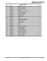
Страница 108: ...Replacement Parts Page 108 MR 380 03 R 380 DC System BRAKES BRAKE LINES...

Страница 109: ...0 00 Brake hose Rear 2 9 99 566 00 Hydraulic Fitting 1 10 99 564 00 T Fitting 1 11 99 572 00 Copper washer 0 564 ID 1 12 99 571 00 Copper Washer 0 500 ID 1 13 99 580 20 Brake Hose Front 2 14 99 604 11...

Страница 110: ...01 Bushing included in rebuild kit 4 5 41 351 35 Brake body assembly no internally serviceable parts 2 6 99 588 01 Bleeder adaptor 2 7 99 588 00 Bleeder valve 2 8 See rebuild kit Brake pad Inner 2 9...

Страница 111: ...Arm 1 2 41 347 00 Backing Plate 2 3 41 347 25 Spider w out wheel cylinder 2 4 85 411 15 Torsion Spring 2 5 41 635 00 Brake Shoes Set of 2 2 6 85 215 00 Spring 2 7 41 347 33 Adjustment Body 2 8 41 347...

Страница 112: ...cylinder 2 4 85 411 15 Torsion Spring 2 5 41 635 00 Brake Shoes Set of 2 2 6 85 215 00 Spring 2 7 41 347 33 Adjustment Body 2 8 41 347 31 Star Wheel 2 9 41 347 30 Socket 2 10 85 411 10 Torsion Spring...

Страница 113: ...270 00 Spring 1 5 96 772 00 3 8 Clevis Pin 1 6 01 380 76 Support Plate 1 7 32 215 00 Bushing 2 8 00 380 77 Bell crank 1 9 96 762 00 3 8 Clevis 1 10 88 119 80 3 8 NF Hex Nut 1 11 50 009 00 Push Rod 1 1...

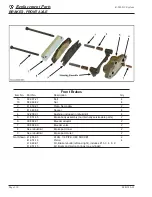
Страница 114: ...Replacement Parts Page 114 MR 380 03 R 380 DC System BRAKES PARK BRAKE LINKAGE...

Страница 115: ...0 11 Hex Bolt 2 11 88 088 61 Flat Washer 2 12 88 089 81 Hex Nut 2 13 51 344 80 Parking Brake Handle 1 14 04 380 10 Cross shaft 1 15 96 343 00 Brake Rod 1 16 88 099 80 Hex Nut 3 17 88 099 81 Hex Nut LH...

Страница 116: ...BUMPER FRONT Item No Part No Description Qty 1 01 380 18 Bumper 1 2 88 109 81 3 8 NC Hex nut 4 3 88 108 61 3 8 SAE Flat washer 4 4 88 100 11 3 8 NC x 1 Hex bolt 4 5 88 080 09 5 16 x 3 4 Hex bolt 4 6 0...

Страница 117: ...indow 1 13 88 065 09 1 4 NC X 3 4 Phillips Head Truss Screw 18 14 88 068 62 1 4 Lock washer 13 15 88 069 83 1 4 NC Acorn Nut 13 16 88 069 81 1 4 NC Locknut 5 17 74 050 00 Windshield Wiper Motor 1 18 7...

Страница 118: ...Replacement Parts Page 118 MR 380 03 R 380 DC System CAB DOORS...

Страница 119: ...2 91 814 11 Right Hinge Female 2 11 88 082 09 5 16 NC X 5 8 Carriage Bolt 4 12 88 089 81 5 16 NC Locknut 4 13 91 011 31 Left Door Unpainted 1 91 011 32 Right Door Unpainted 1 14 90 853 10 Left Window...

Страница 120: ...able components inside the charger Note The charger AC cord is an integral part of the charger When replacing the charger do not cut and splice the AC cord Cutting the AC cord will void the charger wa...

Страница 121: ...9 831 00 Fuse 79 809 61 Relay board assembly Control board assembly 79 749 14 SCR assembly 79 840 02 Circuit breaker 79 849 00 Ammeter 79 810 01 Switch kit start stop low voltage self diagnostic 79 57...

Страница 122: ...10 79 851 10 2 Timer 79 805 69 79 805 67 79 805 72 Relay Timer 79 808 00 79 808 00 79 808 00 3 Capacitor 79 902 00 79 902 00 79 902 00 4 Diode assembly 79 749 13 79 749 13 79 749 11 5 Transformer 79 6...

Страница 123: ...ceable components inside the charger Model QuiQ Model IC650 Item No Part No Description Qty 79 306 37 Charger 36 volt Trojan T105 79 575 09 AC cord 17 foot Item No Part No Description Qty 79 306 32 Ch...

Страница 124: ...Description Qty 79 304 60 Charger assembly spec 7030 01 1 79 851 10 Ammeter 1 2 K4 071 87 Timer 1 3 79 902 00 Capacitor 1 4 79 749 13 Diode assembly 1 5 Transformer 1 6 Cable AC 1 7 79 831 00 Fuse as...

Страница 125: ...er 2 5 88 048 62 10 Lock washer 6 6 88 049 80 10 32 Hex Head Nut 6 7 62 204 00 Controller 1 8 61 838 41 5 8 X 1 2 Bus Bar 2 9 88 099 91 5 16 Thin Pattern Hex Head Nut 10 10 88 088 63 5 16 Lock washer...

Страница 126: ...System Instrument Panel Item No Part No Description Qty 1 71 039 11 Switch 0 or 3 2 74 009 00 Battery status indicator 1 3 71 000 00 Hour meter 0 or 1 4 71 039 02 Switch Direction Control 1 5 71 120 0...

Страница 127: ...FETY WARNING 5X6 E 1 4 94 384 61 DECAL OPS DASH 1 5 94 313 00 DECAL BATTERY WARNING GASES 1 6 94 384 17 DECAL WARNING DO NOT SPRAY 1 7 94 384 14 DECAL LEAVING VEHICLE E 1 8 94 301 57 DECAL DOOR WARNIN...

Страница 128: ...Tailgate Pivot Right 10 00 210 77 Rear Deck Angle 11 30 550 50 Tailgate Chain 12 30 551 00 S Hook 13 30 551 10 Tail Gate Chain Pipe Rails Item No Part No Description 1 00 680 22 Left Pipe Rail 2 00 6...

Страница 129: ...0 not shown Clamp Rubber Lined 3 16 ID 96 630 00 not shown Clamp Rubber Lined 5 8 ID 96 630 50 not shown Clamp Rubber Lined 5 8 ID 265 mounting hole 96 631 00 not shown Clamp Rubber Lined 3 4 ID 96 63...

Страница 130: ...R 380 03 R 380 DC System HITCHES Mounting Hardware Item No Part No Description Qty 97 811 00 1 7 8 inch Ball 97 821 00 2 Inch Ball 88 140 14 1 2 NC x 1 1 2 Hex bolt 4 88 149 80 1 2 NC Hex nut 4 88 148...

Страница 131: ...Description Qty 94 050 11 Headlight Assembly Right 1 94 050 10 Headlight Assembly Left 1 72 025 00 Taillight 2 72 072 15 Bulb Headlight 2 72 072 10 Bulb Front turn signal 2 72 023 59 Strobe light 1 71...

Страница 132: ...t Hinge Female 1 91 814 17 Right Hinge Female 1 10 88 069 81 1 4 NC Locknut 2 11 88 060 22 1 4 NC X 3 1 2 HEX Head Bolt 1 12 88 068 61 1 4 SAE Washer 2 or 4 13 88 065 09 1 4 NC X 3 4 Phillips Truss He...

Страница 133: ...m MOTOR Motor Spec ER5 4002MX Item No Part No Description Qty 70 049 05 Motor assembly 1 1 Field assembly 1 2 Armature 1 3 70 180 00 Brush holder 1 4 80 412 20 Brush spring 4 5 70 109 00 Brush pair 2...

Страница 134: ...0 03 R 380 DC System SEATS Seats Item No Part No Description Qty 90 198 03 Seat cushion Front 2 90 179 00 Seat back Front 1 90 000 00 Seat back Rear fold down 90 177 00 Seat cushion Rear fold down PKI...

Страница 135: ...72 Worm assembly 1 4 18 308 23 Upper worm bearing 1 5 18 308 22 Upper worm bearing race 1 6 18 308 77 Housing 1 7 18 308 78 Seal pitman shaft 1 8 18 308 80 Nut pitman shaft 1 9 18 308 81 Lock washer 1...

Страница 136: ...Replacement Parts Page 136 MR 380 03 R 380 DC System STEERING LINKAGE...

Страница 137: ...11 20 031 44 Steering Shaft 1 12 18 308 21 Steering Gear 1 13 88 128 62 7 16 Lock washer 3 14 88 120 11 7 16 X1 Hex Head Cap Screw 3 15 00 680 13 Pitman Arm 1 16 50 002 07 Steering Sleeve Assembly 2 1...

Страница 138: ...80 3 8 NF Hex Head Nut 4 2 86 006 01 Shock Mounting Hardware 2 3 86 006 00 Shock Absorber 2 4 15 380 33 Front Axle Beam 1 5 88 121 19 7 16 X 2 3 4 NC Hex Cap Screw GR5 2 6 85 506 01 2 Leaf Spring 2 7...

Страница 139: ...kle Strap 2 4 96 248 00 9 16 X 3 Shackle Bolt 6 5 88 109 87 3 8 NC Lock Nut 8 6 85 507 00 Leaf Spring 2 7 88 109 81 3 8 NC Lock Nut 4 8 88 108 62 3 8 NC Lock Washer 4 9 96 123 50 3 8 X 2 X 4 U Bolt 2...

Страница 140: ...4 7 Final gear nut 4 8 80 480 00 Carrier bearing 2 9 Intermediate shaft 1 10 80 715 00 O ring 2 11 66 610 35 Intermediate shaft bearing 2 12 Input shaft 1 13 80 480 10 Input shaft bearing 1 14 80 715...

Страница 141: ...R C 13 742 12 Tire Wheel assembly 5 70 x 8 LR C SPLIT RIM 10 083 00 Tire 5 70 x 8 LR C 13 746 10 Tire Wheel assembly 18 x 8 50 x 8 10 093 00 Tire 18 x 8 50 x 8 13 742 41 Tire Wheel assembly 5 00 x 8 S...

Страница 142: ...Replacement Parts Page 142 MR 380 03 R 380 DC System Notes...

Страница 143: ......

Страница 144: ...other reproductive harm To minimize exposure avoid breathing exhaust do not idle the engine except as necessary service your vehicle in a well ventilated area and wear gloves or wash your hands frequ...

Отзывы: